Welcome to Laser Pointer Forums - discuss green laser pointers, blue laser pointers, and all types of lasers

How to Register on LPF | LPF Donations

Um...some help greatly appreciated....

Joined
Jun 1, 2013
Messages
5
Points
0
I'm trying to wire this green laser diode and driver to a power source but not completely sure on how to wire it up.
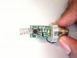
I'm providing a picture of what it looks like. Any help would be greatly appreciated.

Sorry in advance if this is in the wrong section.
 

Attachments

  • phpY3RzEoAM.jpg
    phpY3RzEoAM.jpg
    63.7 KB · Views: 153


Looks like a standard module. Negative to spring. Positive to body. Push the button.
Most use one battery. 18650 etc.
 
Okay so the negative end of the battery to the spring, but where would the positive wire come from?
The black one, or do I have to solder something?
 
Powering it up is going to be easy.

Your next concern will be the fact that you are missing half of that module, in which is included the final collimation lens and IR filter.

In short, your dot will be half meter wide at 2 metres distance.
 
I have lens and all, I just need a way to power it up and put it into the housing.
 
Battery negative to the spring, battery positive to the aluminium sink or brass part in it.

Depending on which host you're putting it in, you may need to bridge the switch to stay on all the time.
 
No luck connecting the battery like that.
Any other ideas? Or if someone could label where to wire, maybe I'm not doing it right.
Sorry guys I'm not very good at this.
I appreciate all the help though.
 
Did you by any chance accidentally contact the battery backwards at some point? Cause, that would be bad. If you connected a 3.7V battery w/ the negative at the spring and the black wire to the positive battery pole, and it didn't work, it sounds like a dead module.
 
No nothing like that.
There was a red wire sticking out from the button and a black I tried connecting them to to the battery and pressing the button nothing happened.
The wire fell out now I have nothing to solder to.
 
Red wire from the button and black one is the one we see in the picture?

Hm, amazing, could it really be this diode has it's input reversed...

Well if nothing else works, try the opposite of how we instructed you and see what happens.

I've actually seen one 532nm (808nm pumped) laser in my life that was case negative.
 
I've had some with wires and a switch. The wires bypass the switch. This is for different operating options.
If you have a good connection to spring and brass body and its not working, I agree its likely dead. Not uncommon.
I got over a dozen of these in the last year and only two are still working properly.
 
To determine case polarity, measure continuity (or resistance) between the brass and L+. Then measure continuity between the brass and L-.


Back
Top