Welcome to Laser Pointer Forums - discuss green laser pointers, blue laser pointers, and all types of lasers

Buy Site Supporter Role (remove some ads) | LPF Donations

Links below open in new window

FrozenGate by Avery

Tesla Coil Build Thread

That linked one is really freaking expensive but as long as it doesnt have a GFCI in it, yes it will work.

To answer your question; it's because the primary circuit is a tuned circuit and the voltage won't just stop rising once it reaches the voltage of the power supply. It will continue to rise uncontrollably until the system reaches an equilibrium point, be that from heavy loading of power transfer or self-destruction. You set the gap so that voltage stops rising at a certain point.


No on the xformer, it is GFI protected

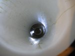
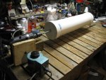
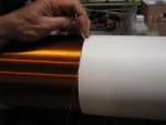
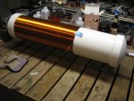
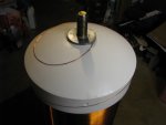
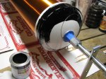
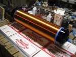
I have been a busy beaver on my 6.6" secondary
 

Attachments

  • IMG_3138.JPG
    IMG_3138.JPG
    98.9 KB · Views: 57
  • IMG_3140.JPG
    IMG_3140.JPG
    112.8 KB · Views: 61
  • IMG_3146.JPG
    IMG_3146.JPG
    197.7 KB · Views: 65
  • IMG_3151.JPG
    IMG_3151.JPG
    112.5 KB · Views: 63
  • IMG_3153.JPG
    IMG_3153.JPG
    190.6 KB · Views: 68
  • IMG_3156.JPG
    IMG_3156.JPG
    111.2 KB · Views: 63
  • IMG_3157.JPG
    IMG_3157.JPG
    207.6 KB · Views: 59
  • IMG_3158.JPG
    IMG_3158.JPG
    219 KB · Views: 61
Last edited:
What do you think of my gap?

Also, I had this question and found the same on another forum, so I copied and pasted.

But the other forum users didn't answer very well.

"what i don't understand is that if the capacitor charges to the voltage of the power supply, only, why would the gap breakdown due to the voltage across the cap and not the voltage across the power supply? isn't the voltage across the power supply the same voltage that will eventually be across the cap"?


So this NST will work? Just wondering. http://www.amazon.com/France-15030-...9730622&sr=8-2&keywords=Neon+Sign+Transformer

Eeek, that's expensive for a NST. I went to a local place that made Neon signs, explained what I was doing and they gave me an old one (10kV @ 30mA) for free (though I gave them a beer voucher by way of thanks). Still surviving nearly 20 years later. I gave it away recently to someone wanting to built their own coil, I graduated to industrial microwave transformers, two in antiphase at over 6kW, though those kept melting my sequential spark gaps, blowing caps and setting fire to the lawn :)

Regarding the spark gap and cap and transformer relationship, if I remember rightly the key to maximum output power is getting the most charge into the cap from a half-cycle, and the problem is the NST transformer's equivalent series resistance. So the voltage on the cap is lower than the transformer's open-circuit output voltage due to the RC relationship between the transformer secondary and cap. But what you measure at the transformer output and the cap in terms of voltage is the same thing (it's after the ESR of the transformer). Perhaps this is where the confusion lies?

I like your gap, that's way better than my first gap (which was just supported with MDF). I always used a fan for forced air cooling. With a telsa coil primary connected the arc is considerably more violent (radiating a lot of UV, Xrays etc so be careful).

It's been years since I built a coil, I love the photo above with neatly wound copper enamel wire. My first one was just normal equipment wire wound around a drain pipe which didn't look anywhere near as tidy :)
 
Last edited:
So today I cut all 28 wire ties and laid down plastic sheeting underneath the primary, on top of the wood.

As the for the transformer, I may buy this one. Transformer High Voltage 60Hz 6kv 30ma EN - Information Unlimited

They recommend using a static gap, so I'll use the one I built the other day. But is 6kv enough?

Would it work?

Anyways, hopefully tomorrow, I'll be able to get a computer fan from radio shack, some aluminum duct (toroid), pie pans, sheets of plastic (capacitors), and some aluminum foil, to replace the kitchen box I used up.

More pictures in the next day or two.
 
Last edited:
Today I bought 10 sheets of 2mm thick pvc. I laid down the aluminum with 1.5cm spacing on all sides and laid them offset. But after 10 layers, I tested charging them with my ballast and they don't charge. I'm wondering if I wired it wrong. My meter shows no continuity opposite plates as it should be, but when I connect a lead from my ballast, (which can arc less than 2mm) to one plate, and touch the other lead to the other plate, it arcs and electricity flows. I don't understand why. It's PVC and the meter shows no continuity.
I'm assuming the way I connected is correct. All the aluminum tabs on each side get connected together with aluminum tape, making to input terminals.

..... equals space. The forum editor doesn't allow spaces like that so I used a period instead.

..---------------pvc
....---------------terminal 1
..---------------pvc
-------------- terminal 2
..---------------pvc
....---------------terminal 1
..--------------pvc
------------- terminal 2

I'm assuming all terminal 1's get connected together, and all terminal 2's get connected together, and both of the combined terminals make the terminals on the capacitor.
 
Last edited:
You have it connected correctly.

For your suggested transformer, 6kV @ 30mA suggests an ESR of 200k (R=V/I).

Your ideal capacitance would be about 13.3nF. Even at 6kV such a cap would only hold about a quarter of a joule of energy (capacitor energy = 0.5*C*V*V), which would quickly leak away through the polythene, so you couldn't expect to charge it then disconnect the voltage source and discharge it through a load.

When you say your test ballast arcs when connected, this is only to the plate you are connecting for the purpose of testing, not that the cap is arcing between the sheets?

Current should flow with your AC power source but not with a multimeter (which uses DC for resistance testing).

My experience of simple aluminium sheet and PVC caps was they didn't last very long under load before hot spots formed between layers of aluminium and melted the PVC, shorting the cap. If you can submerge the cap in oil and use a vacuum pump to extract the air, this will provide a longer life for the capacitor.

But, the air ones do work for a while, and make an interesting rattle noise and glow a pleasant blue in the dark when they are operating. But keep the duty cycle low on the coils use in order not to thermally kill it :)
 
Last edited:
Capacitors don't get charged by AC. Your ballast outputs AC. Capacitors conduct AC; hence the arcing.

This is the basic theory part I posted a while back.


Test the cap in the tesla coil circuit to see how it will perform, there are no easy analogous tests.
 
Wish me luck. I've built a small dam out of plexiglass around the base of the terry filter with a non detergent motor oil filling the base. I hope the whole thing doesn't go up in flames. I have my CO2 powered air cannon with valve open at the ready case things go awry...
 
Okay. But will the transformer I linked work with the capacitor I made you think?

Anyways, the entire capacitor is 14.8nf which seemed pretty big, but I didn't know that capacitors conduct AC. How come? Does it just go through the dielectric?

Wish me luck. I've built a small dam out of plexiglass around the base of the terry filter with a non detergent motor oil filling the base. I hope the whole thing doesn't go up in flames. I have my CO2 powered air cannon with valve open at the ready case things go awry...

Motor Oil+High voltage=:yabbem::mad::eg: I want to here what happens.
 
No fire, no inter component arc that's good. Now I just have a potential mess. After the coil is up and running I will probably build a new TF but for now it will suffice and I can start winding my secondary maybe tomorrow.
 
A couple questions and a few pictures.

1. If I buy that transformer, do I need to somehow protect it from hv kickback?

2. If so, how?

3. Do I need chokes on my coil?

4. Do you think if tuned properly, I could get 6 inch spotaneous discharges.


Lastly, I accuratly measured my plate cap at 2.54nf. Is that enough?
 

Attachments

  • DSC00513b.jpg
    DSC00513b.jpg
    130.9 KB · Views: 55
  • DSC00514b.jpg
    DSC00514b.jpg
    153.2 KB · Views: 60
  • DSC00515b.jpg
    DSC00515b.jpg
    119.8 KB · Views: 55
1, if you use an NST or an OBIT it is recommended you have an RC filter to protect your transformer. People usually make "terry filters" . An MOT or good lord if you can get your paws on a pole pig you won't need a filter.

2, Google terry filter, read HVTESLA or Teslacoildesign.com

3, what chokes are you talking about?
4, I bet you could easily get 6" streams if you actually built a coil.
I can't comment on your homemade cap. I haven't built one.

USAbro, these questions could be answered if you searched around abit. Don't be afraid to read deep into this thread.
 
Last edited:
...but I didn't know that capacitors conduct AC. How come? Does it just go through the dielectric?

It's a lot more complex than that, but essentially that's how it works out for most intents and purposes. Capacitors conduct AC like a resistor, where the value of the impedance (i.e. "resistance") is determined by the frequency of the AC and the value of the capacitance. The nitty gritty made simple is that the applied AC current sets up a continuously changing electric field in the dielectric, and this induces current flow in/out on both sides of the dielectric when the circuit is completed.


Edit: Oh, as I stated before:
ANY NST WITHOUT A GFCI WILL WORK. You have to match the size of the capacitor to the ratings of the nst for decent performance. Depending on the transformer you pick you'll need more or less capacitance.

The 6kV/30ma transformer you linked from IU requires a 25.72nF capacitor for proper operation, roughly ten times the size of your current 2.5nF cap. You'd only get 10% power out of your coil using it.
 
Last edited:
oooooo. Bad to hear. But that just means I need to spend more time making caps.

I can't afford an MMC. What would be the most efficient kind of cap to make at home?

Those plastic sheets I was using are $2 a piece, and I used 10 for that capacitor. That means if I did 10 time what I've already done, it'd cost $200 if I did the math right. That's more than an MMC.

So what's the best option for a capacitor.

Also, today I bought a 6v PC fan. But it hardly puts out any breeze. It is 78cfm. I'm using a 6v lead cell.
 
I've yet to find a DC powered fan that is capable of the wind pressures needed for spark gap quenching. I'm sure they exist, somewhere.

Cheap caps for a TC? Make a Beer-Bottle-Salt-Water capacitor array. Yes, it is lossy. You'll probably lose about 20% of the power you put into it, if not more. But, you're facing a 90% loss right now.

There's only two types of caps I advocate for SGTCs; MMC and Saltwater. One of vastly better than the other, but also very expensive. See: https://www.youtube.com/watch?v=hjqKcRQB3RI for how to make the saltwater caps.

Instead of buying a NST wasn't there someone here who was going to send you one for the cost of shipping? Seems like a better deal.

I can't tell if I'm making all this too complicated or if I'm on the right track.

I would do that but not sure if older family members ;) would be okay with that. Actually I am sure that they are not okay with it. I don't know why. They would be fine if I got one local or bought one though. Strange.

For the caps I may do this. https://www.youtube.com/watch?v=s-e8yaTqhX8

If the fan isn't enough, maybe I could funnel the air through a small tube and shoot it at the gap? Maybe.

Edit: Also, look at this: https://www.youtube.com/watch?v=ACJCUPtCV3I

His capacitor looks just like mine, yet it is 10nf. Using a 7.5kv NST and a 4 inch secondary, he got 3' arcs. So how is mine not reading as much.

Oh, and based on this chart, http://www.justradios.com/uFnFpF.html, and Deepfriedneon, the transformer I link would need 15nf capacitors.
 
Last edited:


Back
Top