

While shopping at Lowe's Hardware for potential parts and tools for my projects, I came across this flashlight for only $18US. It's a single cell AA flashlight based around a boost converter to drive a 1W LED. The boost converter itself is self-contained, and on a separate and enclosed board away from the LED chip. This made it almost too easy to pull and test. Since 1W is fairly close to the expected power in to an LD, I figured it was as good a match as I was apt to find.
Initial test: I hooked up a spare IR LD to see what it could push, and measured about 250mA across it. Slightly high, but within a viable range to work with.
On my next test, I ran a generic 16X DVD burner LD to it and through a 2.2ohm resistor. Current was approx. 185mA, and it was able to light a match with ease. Right now, I'm wishing I had a good laser power meter to see exactly what it was producing. Oh well, I found a good, safe spot to go for, so on to the build!
1 16x DVD burner LD (GB diodes are perfect!)
1 Aixiz 12mmx30mm housing
1 3/8" flat washer
1 2.2ohm resistor
1 uF capacitor
1 918-type diode
Beyond the obvious basics, I had a few tasks at hand:
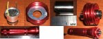
I had to cut the outer diameter of the washer back enough to fit inside the housing. I cut it small enough for it to rotate easily, but not so small that it was falling free.
The Aixiz housing (rear portion) was cut short by a few mm for it to act as a proper spacer and hold everything in place after assembly. I also cut notches in the side for the wires to emerge without being crimped against the driver housing.
The 1W LED board was removed from the assembly. The wires were left as long as possible for ease of connection and further testing.
Here's the simple circuit wiring:
+-------+
| Y| (+)
| +--/\/\/--+----+----+
| Boost | 2.2ohm _|_ | |
| Conv. | /_\ === L D
| | | | |
| +---------+----+----+
| K| (-)
+-------+
Very simplistic, and yes, there is a chance of LD blowout. With further work, someone could probably fit a small regulator in the housing, but the LM317 wouldn't regulate properly after this boost circuit.
I realize this isn't exactly a how-to, but I hope it has provided a bit of insight and another choice for those unable or unwilling to acquire the other options.
Initial test: I hooked up a spare IR LD to see what it could push, and measured about 250mA across it. Slightly high, but within a viable range to work with.
On my next test, I ran a generic 16X DVD burner LD to it and through a 2.2ohm resistor. Current was approx. 185mA, and it was able to light a match with ease. Right now, I'm wishing I had a good laser power meter to see exactly what it was producing. Oh well, I found a good, safe spot to go for, so on to the build!
1 16x DVD burner LD (GB diodes are perfect!)
1 Aixiz 12mmx30mm housing
1 3/8" flat washer
1 2.2ohm resistor
1 uF capacitor
1 918-type diode
Beyond the obvious basics, I had a few tasks at hand:
I had to cut the outer diameter of the washer back enough to fit inside the housing. I cut it small enough for it to rotate easily, but not so small that it was falling free.
The Aixiz housing (rear portion) was cut short by a few mm for it to act as a proper spacer and hold everything in place after assembly. I also cut notches in the side for the wires to emerge without being crimped against the driver housing.
The 1W LED board was removed from the assembly. The wires were left as long as possible for ease of connection and further testing.
Here's the simple circuit wiring:
+-------+
| Y| (+)
| +--/\/\/--+----+----+
| Boost | 2.2ohm _|_ | |
| Conv. | /_\ === L D
| | | | |
| +---------+----+----+
| K| (-)
+-------+
Very simplistic, and yes, there is a chance of LD blowout. With further work, someone could probably fit a small regulator in the housing, but the LM317 wouldn't regulate properly after this boost circuit.
I realize this isn't exactly a how-to, but I hope it has provided a bit of insight and another choice for those unable or unwilling to acquire the other options.


") I'd stop there as that's about the best you can do but make sure you watch the heat. I presume you have an Aixiz module for simple mass heatsink. Don't increase unless you have this heat disapation.
I'd stop there as that's about the best you can do but make sure you watch the heat. I presume you have an Aixiz module for simple mass heatsink. Don't increase unless you have this heat disapation.