Welcome to Laser Pointer Forums - discuss green laser pointers, blue laser pointers, and all types of lasers

Buy Site Supporter Role (remove some ads) | LPF Donations

Links below open in new window

FrozenGate by Avery

Suggestions on variable DC power supplies/oscilloscope discussion.

You're killin me LSRFAQ, I just bought the 1054Z. I agree, the interface and control panel are "cluttered" and "busy" it will be something to get used to. The larger screen is nice and at least there is an option for four channels even if there is limited bandwidth.
It's very unlikely I will perform the hack.

Right now I'm reading "The XYZs of oscilloscopes" and using the basic functions on the scope so I maybe better learn how to use it and what applications to use it for.
XYZs of Signal Generators | Tektronix

thanks all who have contributed to this thread.
 
Last edited:


I send all the students I work with to "XYZs", its a good read.
Even better if you can find the old "analog" edition some place.

The 1054Z still has a lot more memory then most of its competitors, so you win there...
Also Rigol DOES do bug-fixes and software updates.

Steve
 
Last edited:
Yep, I wouldn't regret the 54z really. You're leagues above and beyond competition... and the rest of us on old analog clunkers. The price is only user friendliness, and that you can overcome with dedication*.

*occasional fits of frustration may occur. ymmv.
 
EEVBLOG has some very useful information indeed, especially comparing digital scopes available. Dave can be a bit of the top complaining about little things in teardowns but clearly knows what he is talking about.

There remain some properties of analog scopes that are worth having though. Easy of use for the beginner is certainly one of them. No menu's to muck around with, just a few dials that set how big a signal looks on the display and one to set how fast the dot moves across.

Simple analog scopes will not tell you the RMS value, frequency or even fft breakdown of a signal, but are in my experience superb when you don't really know what to expect from a signal and go about it by switching through timebases and amplifications quickly.

If you want numbers, use a multimeter ;)
 
I do have a Fluke 87 5 that reads RMS but I would like to visualize the waveform.

I don't want numbers, I want to see it damn it!
(Or at least the scopes interpretation)

Are the vectors really deceiving or when looking at some readings you view "dots"??
 
Last edited:
RMS functions on multimeters are somewhat limited - often there is a rather low maximum frequency it can work with (couple of kHz), and also a certain minimum: If you have a signal that is 5 volts for half a second then 1 volt for another half a second, it will not read a steady 3 volts.

For specific stuff like that digital scopes can be very convenient. With the analog scopes you would work such things out by taking a long exposure off the screen using a camera and figure it out from the image produced - guess that's kind of a 60s - 70s experience :D
 
Hey friends,
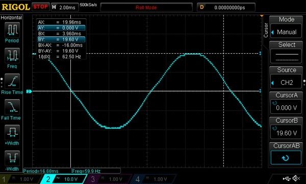
today I have been practicing taking readings with this scope. First victim- scoping the AC output from a variac.
One thing I immediately noticed was the difference from the DMM and the scope. :thinking:
I used the meter to set the output to 20.36volts then I connected prob to the hot lead out. Measured something different. Hmm. I then carefully adjusted the variac to 20volts per division and used the measured again with the DMM and got 13.96.
Why the difference? I KNOW the answer is something simple I just am breezing over it. I know DMM tend to take averages...something to do with RMS. for the screen shots I had the mode set to roll but I've been using the XY and various other triggering options. Still working on those.

Simple sinusoidal wave form.


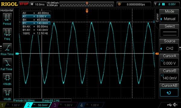
What I thought was really cool was even when the variac's switch was "off" there was still what appeared to be 140mv bypassing the switch.


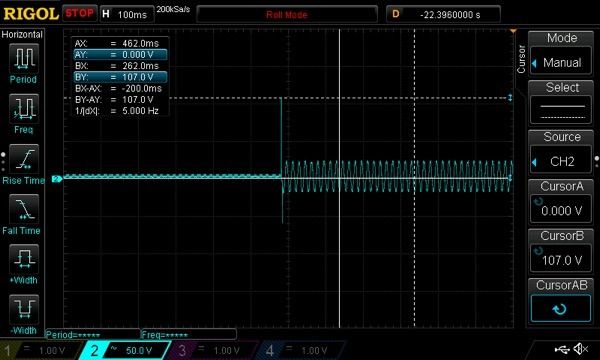
Yikes, look at that spike when turning the power back on. (Ignore the X cursors, I didn't know where to put them.)

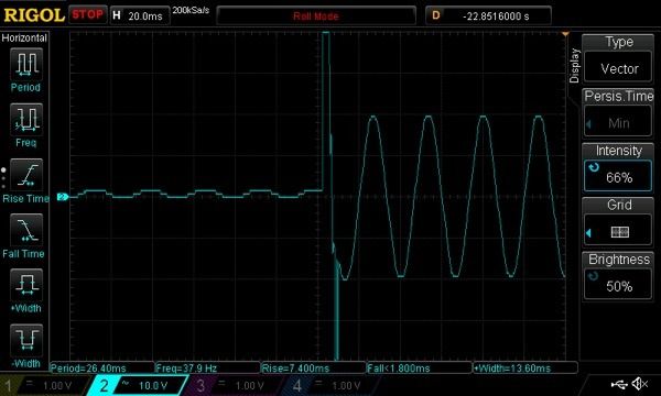
Slightly closer look.


So far according to the timer I've logged about 9hours with the unit on.
Before last week I've never used one before. It's really cool on all about circuits website they have some worksheets with problems and answers. I've found that helpful: Basic Oscilloscope Operation : AC Electric Circuits Worksheets

EEVblog has been great as well.
 
Last edited:
The meter is probably giving you an RMS ( root mean square ) reading while the scope is measuring peak to peak.

I saw that you were measuring a 20 volt peak to peak with your meter and the value your meter gave is off. For a 20 volt sine wave, the RMS voltage should be 14.14 Volts RMS. But, it's not off by much. :)
 
Last edited:
Indeed, though the scope should be able to give you RMS just as well - probably a matter of finding the desired setting for that.
 
Since it hasn't been said before: be VERY careful when scoping mains powered equipment because if you connect HOT anything to the ground on a scope probe you will have a very expensive repair or replacement on your hands. A variac does NOT isolate the mains, it is a simple autotransformer and has a direct DC link from Hot on the wall to the output. Some variacs are wired up in reverse too, and the end users never know it (I had one like that, I rewired it after finding out). Even if the device being scoped is switchmode (like an inverter or ac-to-dc-dc converter) it may not isolate from mains.

Yep, RMS of a sine is 0.707 * Vpk (not Vp-p). To go the other direction it is RMS * 1.414. Meters won't show Vpk or Vp-p.
 
Roger that. Be extra careful when attaching the probe to anything that's not "floating". The BNC connectors have a direct path to ground earth!
I probed the Variac first to confirm which was hot but as you pointed out clearly not everything should be assumed this way.
This reminds me to check my PS HY15v3A. It doesn't have a dedicated GREEN earth like the mastech has.

RMS, thanks for pointing that out to me Paul, BenM is probably right about it being in some sub menu measuring option. I suspected this was involved but wasn't sure enough to say so with certainty. Learning a lot the past weeks.
On this weeks agenda are testing out differential measurements with two probes and tackling tuning the spark gap Tesla coil.
IIRC the secondary resonant frequency was 220.79 kHz. Setting the primary just under that will yeld better results because the streamers shift the capacitance.
This will be something I research more tomorrow. Zzz
After a late Star Wars showing I'm zonked.
 
Last edited:
This reminds me to check my PS HY15v3A. It doesn't have a dedicated GREEN earth like the mastech has.

Virtually all oscilloscopes measure a waveform with respect to ground. Since any voltage measurement requires two contact points, one of those contact points will always be ground.

Virtually all bench power supplies are floating by default - both of yours are. To scope anything, one end (either the positive post or the negative post) needs to be grounded. Two convenient grounding points are the "green" binding post and the scope's ground lead itself. You can use either or both, but the scope probe's ground lead will offer a lower noise waveform, generally. Simply put, you can scope a bench PSU like you would a battery... no precautions involved. Just be aware scoping anything (including batteries) grounds one end.

There is one trick around using the ground reference for everything. That is to use two channels, and use a scope function (math: Channel1 - Channel2) which will take the reading of one channel and subtract it from another. If needed, this allows floating measurements without the need (or potential danger) of grounding. This makes it more like a handheld DMM where channel 1 is the "red lead" and channel 2 is the "black lead". The disadvantage of course is it needs two channels.
 
Practical implications of grounding are a bit variable. In europe we have lots of wall sockets without any ground connections, and you can plug a scope into those just fine. It's quite common to have grounded sockets only in kitchens, bathrooms and places you would rely on a ground fault detector under normal conditions.

The scope is electrically insulated from the phase and neutral mains connections (via a transformer) so this is not that problematic. You can do relative measurements in low voltage systems (i.e. measure over a laser diode which is hooked between +VDC and a floating point fed from a bench supply).

Practically this often works just fine, but there are some caveats. Some bench supplies, for example, have their negative output conntected to earth and/or the metal enclosure. If you put the metal case of the supply on top of the metal supply of the scope you can create a ground short there.

You could check if your bench supply has its negative output connected to ground and/or the enclosure using a multimeter quite easily. Most will not, but i've seen some that do, mostly very old units.

If you have a scope that can display differential between two channels that's great. Keep in mind that there often is a limit to how much voltage is allowed between the middle pin and the shield of the BNC input though. For low voltage this is no problem, but don't to measuring stuff on the hot side of mains powered circuits without checking the limit!
 
Thanks benm, I forgot to reply. This thread has been insightful.
Alright guys I have a new item to test.

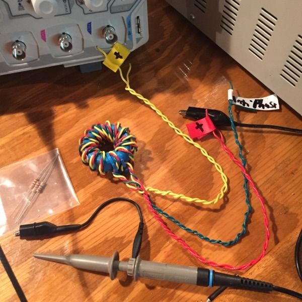
For my SSTC I have wound my own GDT. As per Sigurthrs youtube video I am 90% sure I have my phasing/polarities correct.
GDT- 1:1:1 ratio, 15turn, 22g solid core wire. The green lead is the one I have crossed.
I would like to use my DSO to check this and with no signal generator I was hoping to use the scopes built in 1kHz generator to verify. (I'd like to confirm my phasing/polarities are correct)

Does anyone have advice how best to do this?
Is it as simple as hooking up a battery and 1kHz generator to one side then scoping across the output(green wire) with a shunt resistor?
 
Last edited:


Back
Top