Welcome to Laser Pointer Forums - discuss green laser pointers, blue laser pointers, and all types of lasers

Buy Site Supporter Role (remove some ads) | LPF Donations

Links below open in new window

FrozenGate by Avery

Step down circuit for laser control, help me to improve it.

I've already implemented an EMI/RFI filter in the power supply (the X1 X2 ones), I'm using an exclusive source for the laser, but same ground due communications. Some experiments with LM317 using TIP41C transistors, and LM338 experiments, shown me that linear systems are not good for the laser control. Other point is my dutty cycle is limited at 45% due inverse amplification Q2. You didn't answered my question.
Or you know, stop being so stingy and just use an off the shelf current regulator that would require 4 external components, Will be a lot more stable, smaller more efficient and have proper modulation capabilities.....
Again do you realize this is a waste of an STM32? Not only is the switching freq so low that you need output caps in the 1000s of micro farads that would absolutely fuck any diode you happen to connect to the output if you didn't discharge them, But the current control loop of the IC will be WAY slower than an actual switching IC... Stop kicking the dead horse.
It is true that higher frecuencies (500khz or higher) are better for the control, but using a simple IR2100 allows to control that, I mean, I dont want to make the same thing that all hobbyists does, with the first circuit my results were excellent (you have the proofs there), if an P controller on electronics is slow for your opinion... well... that's not true, but I'll read more any case (and you definitively should). An F411CE is not a waste resources, 100MHz of clock work are more than good, there are other peripherics as an menu control than I'm using. The only dead horse that is being kicked is yours, not mine, let go and live men.
 
It is true that higher frecuencies (500khz or higher) are better for the control, but using a simple IR2100 allows to control that, I mean, I dont want to make the same thing that all hobbyists does, with the first circuit my results were excellent (you have the proofs there), if an P controller on electronics is slow for your opinion... well... that's not true, but I'll read more any case (and you definitively should). An F411CE is not a waste resources, 100MHz of clock work are more than good, there are other peripherics as an menu control than I'm using. The only dead horse that is being kicked is yours, not mine, let go and live men.
Excellent? Care to back that up? Get a voltage ripple measurement and current ripple, If you are talking about your previous results they were pitiful, Also saying that you could utilize a 100MHz clock with this just shows how much knowledge you really have with switching converters.. Furthermore, you act like I couldn't easily get the same menu options with a smaller STM32 like an F051K6T6 and the PWM input on all of my drivers, Such a joke! Again you should go with my recommendation, Use your STM microprocessor as you want to implement menus but actually build a proper CC SMPS with it, I'll even recommend you a part, https://datasheet.lcsc.com/szlcsc/1804170012_Analog-Devices-LT3956EUHE-PBF_C107924.pdf There you go, Amazing part from linear whose freq can be adjusted with a digipot and has a PWM pin.
 
I don't know a thing about ICs, but I know they sure are cheaper than microprocessors... at least from a cost perspective using an STM32 doesn't really make sense
 
I don't know a thing about ICs, but I know they sure are cheaper than microprocessors... at least from a cost perspective using an STM32 doesn't really make sense
That specific LT part is costly but as you can see made for the job and jam-packed with features, FYI LT is the duck's guts in terms of driver ICs, Best of the best.
 
Don't fucking lie to us. You've ignored all advice you were given, time and time again. Just leave.

That specific LT part is costly but as you can see made for the job and jam-packed with features, FYI LT is the duck's guts in terms of driver ICs, Best of the best.
Cyparagon called it in post #5 and the OP's other thread pretty much tells the same tale.
The OP doesn't want help or advice, it seems.

The OP is fixated on/obsessed with $5 STM32 Development Boards.
Maybe he doesn't have much in the way of resources or experience other than books--who knows?
Is a Universidad Nacional de Ingeniería/UNI guy in Nicaragua who posts programming for STM32 and puts together devices with same .
You can see where he s coming from on his wordpress posts which include his bits about a laser driver
See his "electricaldarkness" posts here : https://electricaldarkness.wordpress.com/
Is all just doing what people have done with STM32's that are all over the web and on YouTube.
There are millions of listing on goggle about STM32s .
 
Last edited:
If its a specific challenge the op has given themselves: to build a driver using an STM32, then that's a different story
 
Cyparagon called it in post #5 and the OP's other thread pretty much tells the same tale.
The OP doesn't want help or advice it seems.

The OP is fixated on/obsessed with $5 STM Development Boards.
Maybe he doesn't have much in the way of resources or experience other than books--who knows
Is a Universidad Nacional de Ingeniería/UNI guy in Nicaragua who posts programming for STM32 and puts together devices with same .
You can see where he s coming from on his wordpress posts which include his bits about a laser driver
see his "electricaldarkness" posts here : https://electricaldarkness.wordpress.com/
Is all just doing what people have done with STM32's that are all over the web and on YouTube already.
There are millions of listing on goggle about STM32s .
Sr. that doesn't contribuite to the post, actually was kind of awkward, and most importantly you're not contribuiting to the post or the circuit., I'm waiting for your advices. BTW, I didn't knew that you are a big fan of mine! if you wanted my autograph you only needed to ask for it.
If its a specific challenge the op has given themselves: to build a driver using an STM32, then that's a different story
Sr. that doesn't matter, LVCMOS can be obtained with the Pi Pico or Pi 2B, or even changing to a NEXYS A7 with TTL, the trigger is almost the same, or you can continue playing with your freaking arduinos. I'm waiting for your improvements.

What's the matter with all the guys here ha? a little scared that a third world country boy is posting ideas based with evidence? I'm still waiting for your supporting ideas on the circuit.
 
I don't think anyone wants to help you now at this point. Not being mean just being honest.
 
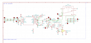
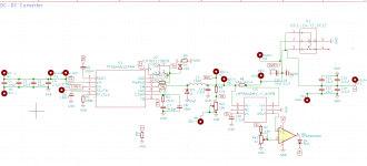
Oh here's my idea! An actual working circuit:
{updated scem below}
1-30v 0-5A with input capabilities of 9-48v. I have also designed it from the ground up to be able to support a processor board I have made for it consisting of 2 Adcs and 1 stm32 which will be used to read out the current and voltage with ~ at least 4.5 digit resolution and will have a nice GUI. What happened Mr 3rd world country, Did a teenager from a poor country just shit over you?
 

Attachments

  • 1614926020240.png
    1614926020240.png
    140.9 KB · Views: 13
Last edited:
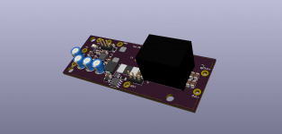
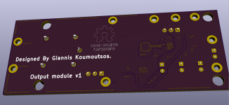
Fancy a PCB too?

unknown.png

1614956401528.png
1614956445840.png
1614956614341.png
If you want to use it don't remove that "designed by{my name}" line
And the BOM: https://www.mediafire.com/file/hdywgugd69v43b9/LCSC_Exported_20210305_230439.xlsx/file
Disclaimer: I have not tested it yet hence no PCB file, I would strongly advise against building it till I have confirmed every aspect of its operation.
 
Last edited:
Oh here's my idea! An actual working circuit: View attachment 71911
1-30v 0-5A with input capabilities of 9-48v. I have also designed it from the ground up to be able to support a processor board I have made for it consisting of 2 Adcs and 1 stm32 which will be used to read out the current and voltage with ~ at least 4.5 digit resolution and will have a nice GUI. What happened Mr 3rd world country, Did a teenager from a poor country just shit over you?
Your circuit looks awesome! I like the focus filters that you desing, really good use of KiCAD as well. R8 is used as R_Shunt? are the 10miliohm used on porpuse to limit the effects 'cause the internal thermal resistence of the laser, and current feedback? Are you using the datasheet or are you measuring the value with an equipment? The used of TPS is based on the price or provides more efficiency than TPS56C215. BTW you give an idea, insert electromechanical control in the PCB itself for FAN control. Where is the over tempeture protection for the circuit? I'm not seeing any of that in that circuit.
Fancy a PCB too?

unknown.png

View attachment 71912
View attachment 71913
View attachment 71914
If you want to use it don't remove that "designed by{my name}" line
And the BOM: https://www.mediafire.com/file/hdywgugd69v43b9/LCSC_Exported_20210305_230439.xlsx/file
Disclaimer: I have not tested it so I would strongly advise against building it till I have confirmed every aspect of its operation.
Why purple? is a protocol stablished for laser PCB's? I'll make it on SMD technology the SOP circuit that I have.

Note for the forum on post #1: I didn't considered BC547 efficiency, I have to use a base resistor of 12K, and a base ground resistor of 100k. The ilogical point is that no body didn't noticed that...
 
A little off-topic, somebody give the OP the award for the longest member name! :D
 
Yes, R8 is a 10milliohm shunt for both efficiency,tempco and stability reasons, Its drop is amplified by a dedicated IC 20x to accommodate for the lower value, The components I have calculated myself using the formulas in the datasheet, I chose that IC due to its high current output capabilities, Heatsinking is not a problem, Its stitched to both the ground planes, OTP is inside the IC. Also purple because I order my PCBs from osh for all of my drivers so I have pre-set it to that.


Back
Top