Welcome to Laser Pointer Forums - discuss green laser pointers, blue laser pointers, and all types of lasers

LPF Donation via Stripe | LPF Donation - Other Methods

Links below open in new window

ArcticMyst Security by Avery

Selling: 3x 2A driver with Userinterface for RGB Control

farbe2

Well-known member
Joined
Oct 3, 2018
Messages
303
Points
63
Hello Guys,

I did make a 3 channel driver that can be used as the complete control electronics needed for a RGB laser pointer.
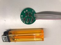
IMG_9386.jpg

Features:
- 3 Channel with up to 3x 2A completely spike/surge free
- MM config (950mA Red / 2A Green / 1.7A Blue) or SM config (250mA Red / 350mA Green / 250mA Blue) or Custom as you Like
- each channel is analog dimmable
- 2x 18650 lipo voltage input (6-9V input)
- Battery state can be displayed with RGB led output
- Battery under voltage lockout to protect against battery over discharge/damage
- over temperature protection
- reverse polarity protection
- short circuit protection
- Very small 27mm diameter 5mm thick
- high efficiency buck current sources for long battery runtime and
- no cooling needed for the MM / SM config
- Userinterface (for color control / mode select) with rotary encoder
- fast color modulation for Rainbow circles/Lines/spirograph
- multiple automatic colorchange modes with brightness and speed adjust
- brightness adjust for each color to mix the color you like
- last used brightness and color gets saved
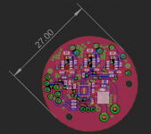
pcb.png
The driver has a rotary encoder interface. It features a RGB led output to show the current state. Can be used with a RGB rotary encoder.
The encoder is used to select the color and disable/enable the laser.

The software currently offers dimming of the 3 colors for color mixing. There are also color fading modes -> RGB fade -> Color switch -> random Color -> Random Vibrant Color.
While the automatic color fading modes are running, the speed and brightness can be adjusted.

Price will be 89,99€ for the normal version (multimode) excluding shipping.
The price will include one fully assembled PCB and a RGB rotary encoder with translucent knob.
You only need to connect the diodes to the PCB, connect the rotary encoder and supply power.
Solderpads are through hole, so should be easy to insert wires and solder them on.

Shipping will be from EU to everywhere.
 
Last edited:


farbe2

Well-known member
Joined
Oct 3, 2018
Messages
303
Points
63
Update:
I did make a video showing my RGB Laserpointer with this driver.
It shows the menu system and explains the userinterface of this driver.
As YouTube does not seem to work link: youtube

Clarification:
This driver can also be used for a single or multimode laser module.
If you want to build a laser with for example a opt laser RGB module or a cheap 60$ Chinese 350mW RGB module. This driver would work beautifully. It includes all circuity needed for driving the diodes. So the original driver of the Chinese module would not be needed. Just connect my driver and off you go. Full RGB control in your hands.

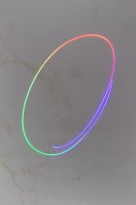
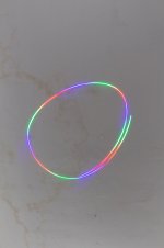
The driver does some tricks to let you draw colored circles for example.
Have a look:
rainbow_slow2.jpg
rainbow_fast2.jpg

This is a picture of the driver in RGB color fade mode. If this mode is chosen and the speed is turned up all the way, the colors are faded fast. This will make it possible to move your pointer around and draw circles.
 
Last edited:

Tankdogtf

New member
Joined
Mar 2, 2021
Messages
2
Points
3
Ooh farbe2!! You wouldnt be making anymore of those rgbs to sell would you? Beautiful laser pointer!
 

farbe2

Well-known member
Joined
Oct 3, 2018
Messages
303
Points
63
The current is set by him through software.

The current is not set through software. Its set by changing components on the PCB.
Each buck converter stage uses a single 0603 surface mount resistor to set the current. This resistor needs to be desoldered and soldered to change the drive current for the respective channel.
So 3 resistors in total need to be changed if you want to change the current after delivery.
This can be done but you need to have appropriate soldering skills to not destroy the board.

Thats the reason why i want to know your drive currents, this simplifies the setup process for you so you dont need to calculate and solder components.

Two standard versions exist:
Multimode for around 3,3W output which would be used for a combination of the 700mW red (GH0637AA2G), 1W Green (NDG7475) 1,6W Blue (PLTB450B) for 0,95A, 2A and 1,7A respectively.

Singlemode for around 600mW output which would be used with following diodes: 185mW Red (GH0631IA2G), 120mW Green (PLP520) and 80mW Blue (PLT5450B) with 250mA, 350mA, 250mA respectively.

For every buyer I will provide a soldering (which wire goes where) diagram and the needed formulas for calculating the resistor value.
 

FAP

0
Joined
Apr 9, 2013
Messages
43
Points
8
Diodes are:

1. Two red diodes powered in series: ML501P73 638nm 500mW+ Orange-Red Laser Diode, with two; total power is 1+ watt of red at 800 mA. I already killed one of these pushing them too hard.

2. NDG745T 525 nm 1 watt green at 1.8 amps, go ahead and set o 2.0 amps.

3. NUBM0AT 455 nm 4.5 watts at 3.5 amps, please set to 2.0 amps due to driver limitations, but I believe this one should not be driven to full output due to RGB color balancing anyway.

This is already built, it is a 5 watt RGB from techhood (I replaced their 700 mw green diode running at 1 watt with a NDG7475T due to failure).

I am putting this in a pointer host. This might not produce the 5 watts it was designed to make with your 2A driver max current (because blue might need more), if so, that's OK, won't get as hot in the pointer that way.

Chris
 
Last edited:

farbe2

Well-known member
Joined
Oct 3, 2018
Messages
303
Points
63
Nice build idea, even with blue at 2A it should be way more power than needed anyway!
Color-balance should be ok 1W of red is more than my pointer is doing, i get around 600mW red, 1W green and 1,5W blue after apature.
I finde the colorbalance quite nice. Could be a little more red, but blue an green are good.
Looking forward to your build, would be nice if you post your progress!

Let us do the rest via PM.
 

FAP

0
Joined
Apr 9, 2013
Messages
43
Points
8
PM sent with my email addy. Total of 3 each.
 
Last edited:

farbe2

Well-known member
Joined
Oct 3, 2018
Messages
303
Points
63
Update for everyone:

I added a new color fade mode, it fades between random colors. So ist close to the random color jump mode, but it fades smoothly between the colors.

I also have bad news:
Some parts for the driver are currently not in stock everywhere. Especially the microcontroller. So please don´t expect a fast delivery. I can't do anything about that.
 

farbe2

Well-known member
Joined
Oct 3, 2018
Messages
303
Points
63
Transaction with FAP was successful, he purchased 3 drivers specially configured for his two red diode setup.

I still have PCBs left. Just write a PM or post in this thread.
 

farbe2

Well-known member
Joined
Oct 3, 2018
Messages
303
Points
63
I give myself a little push because i noticed someone was thinking about building a RGB handheld.

also:
There are a few updates to the software.

I have written a "one color" firmware for a buyer. The 3 drivers work in parallel for use with multiple same color diodes. The board only does strobe and dimming with this firmware.

I also include the software source code thats fully commented for self modification if someone likes to change the behavior of the board or add special color modes.
Its simple to program with Arduino software on Mac/Windows and just needs a very cheap Arduino nano (10USD) to upload the new modified firmware.

Driverboards still ship with stock firmware that i also use on my pointer. I could also ship with the one color mode, if you like.


Top