Welcome to Laser Pointer Forums - discuss green laser pointers, blue laser pointers, and all types of lasers

Buy Site Supporter Role (remove some ads) | LPF Donations

Links below open in new window

FrozenGate by Avery

RGV - full color scanline

Joined
Feb 15, 2010
Messages
31
Points
0
Hi, I'm new here and a n00b with lasers, so don't get mad at me :p

I'm studying electrical engineering, and I have no problem using dsp and microcontrollers/microprocessors.
I want to try to make a scanline RGV laser projector, but I need some help.
1) Can I dim the laser intensity with a PWM signal as with LEDs?
2) Where I can find a precision two axis motorized mirror?
3) In order to merge R, G and V beams what I have to use? Dichros, prisms or a convex lens?

I think the convex lens, if well built, can be a good way to superpose those three channels. You have only to be precise and do some optic calculations.

Thank you for your support, Riccardo

PS: I took the idea from this Microvision: How The PicoP™ Display Engine Works


Yes you can use a PWM signal with lasers, the FML RGV driver uses PWM. However, most laser projector systems usually use analogue modulation to achieve the needed colour blend.

The best option for a "two axis motorised mirror" would be a galvonometer set.


Lasershow Parts

Chinese Department Store

These are able to scan images and animations, but not like the ones on the site you linked to. Below an example of a graphic scanned by a set of galvonometers.

IMG_8067.jpg


If all you want to do is scan a line it would be far simpler to use a rotating polygon mirror in order to achieve a line effect. They can be found in old laser printers - someone here might have some for sale.

To merge the beams you would use Dichros which reflect/pass the colours in order to mix them. Here is an example with just red and green making yellow:

23758d1255424599-first-rgy-spirograph-dichro-comb.jpg


If you wanted to add violet then you would get a dichro which passes red and green and reflects violet. Or passes violet and reflects red and green.

The best way to combine beams of different wavelengths would be to use Dichros.
 
Last edited:
thank you for your fast answer

I realized that this hobby is truly expensive lol

I can say I'm trying to build a laser CRT XD

I looked for polygonal mirrors and I saw they are very useful but needs a particular curve lens (scanning lens in the picture)

laserscanning.gif


What will happen if I don't use that lens? Will I get a distorted image?

I found some possible sources of polygon mirrors:
link 1
link 2
link 3 - razordata 9000

which one would be the best suited? The last one looks very interesting, but is gold a good mirror for a full color beam?

and what about this cheap galvanometer (35$)?
Or two stepped motors and two mirrors?
 
Last edited:
As far as mixing the colors, you don't have to reinvent the wheel thanks to member sightfx and others. sightfx sells a ready-made kit that is specifically designed to mix a red diode, a violet diode, and a green dpss module into one output. Look for it in the Pro Shop section, it's called the White Fusion kit.

It makes combining the colors a lot easier, then you can put whatever other optics you want in front of it.
 
thank you for your fast answer

I realized that this hobby is truly expensive lol

I can say I'm trying to build a laser CRT XD

I looked for polygonal mirrors and I saw they are very useful but needs a particular curve lens (scanning lens in the picture)

laserscanning.gif


What will happen if I don't use that lens? Will I get a distorted image?

I found some possible sources of polygon mirrors:
link 1
link 2
link 3 - razordata 9000

which one would be the best suited? The last one looks very interesting, but is gold a good mirror for a full color beam?

and what about this cheap galvanometer (35$)?
Or two stepped motors and two mirrors?

You don't need the lens after the mirror, it's for focusing the beam to get a sharper image on the paper.

I'd probably go with the first polygon scanner. The third one should work too, but I'm not sure what difference the gold would make when using more than one colour of light. But remember, you cannot scan an "image" using the polygon mirror scanners, all you will get is a line.

That isn't a galvo set, it's more like a set of speakers with mirrors on it. They do not have a rotational motion and while they can scan - they are not what you are looking for if you intend to scan graphics.

I see you've found Photonlexicon.com , if you go over there the guys on that forum can help you out if you want to build an RGB/V that can scan graphics/animations. They know what they are doing when it comes to that.
 
Thank you for the infos, I'll try to ask photolexicon.
BTW, if I use the blue dichro that comes in this auction with a purple 405nm laser what the effect will be? A partial absorption?
Can I use those dichros to make an RGV set?
Where I can find dichros?

Thanks

EDIT: which one gives the best beam? The PHR-803T or the KES-400A sled?
I can find the PHR for 14 usd (includes working diodes) and the KES for 19 usd (defective module - have to buy all the diodes). The PHR mod uses a beam splitter and a dichroic lens, though the KES uses two beam splitters. I don't know why but I find the KES as more intriguing even if more expensive :P
 
Last edited:
RGB to RGV

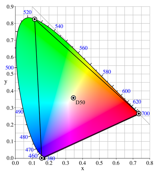
Assuming that with two polygon mirrors you can make a full RGV frame (TBD), have someone the gamut values for a laser RGV system, so that I can directly develop a circuit which takes the R, G, and B values and gives a new RGV system color signal?
Can I simply use a triangle in the color space with vertices placed on the border of the curve in proximity of the 405, 532 and 650 nm values, like the Adobe Wide Gamut RGB color space?
542px-CIExy1931_AdobeWGRGB.png

I also read that the 405nm laser, if projected over a rough white surface like paper, appears blue. Can I take advantage of this effect and use a simple RGB signal?
Thanks for your help, Riccardo
 
Last edited:
One problem with the polygon mirror: For a TV display, the horizontal scan has to be darn fast. Standard TV requires 15.625 kHz, equates to about 1.000.000 scans per minute. A six-sided mirror would have to spin at a whopping 160.000 rpm to achieve that.

It may not be impossible, but may not be easy to do either!
 
In short, yes, you can get pretty close with just a triangle on the CIE chart, with the corners on the edge of the CIE chart. The only real problems are that, especially the diodes, are still not 100% spectrally pure, and the diodes can vary in wavelength by +/- 5 to 10 nm from diode to diode (but each diode will stay pretty consistent).

So while to be completely accurate you couldn't put the corners on the edge of the CIE chart, doing so will still get you really close. Once you have that starting point, you can adjust from there ti get the white balance that looks good to you and takes into account your unique diodes and their unique wavelength(s).

Here's an example of the analysis by sightfx when designing his RGVs. None of the lasers have come out exactly to these powers, especially after you have to take into account optical losses (and these numbers are all for after optics, btw) and the variance from diode to diode, but it's a good starting point.

http://laserpointerforums.com/f64/fs-white-fusion-laser-mixing-kit-42013.html

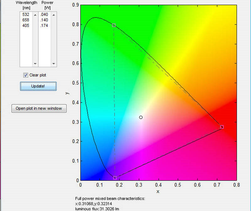
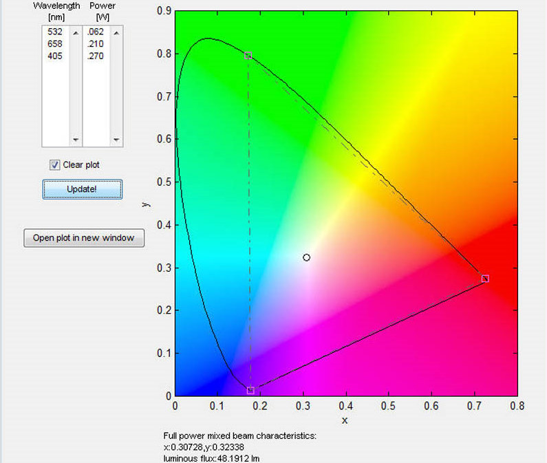
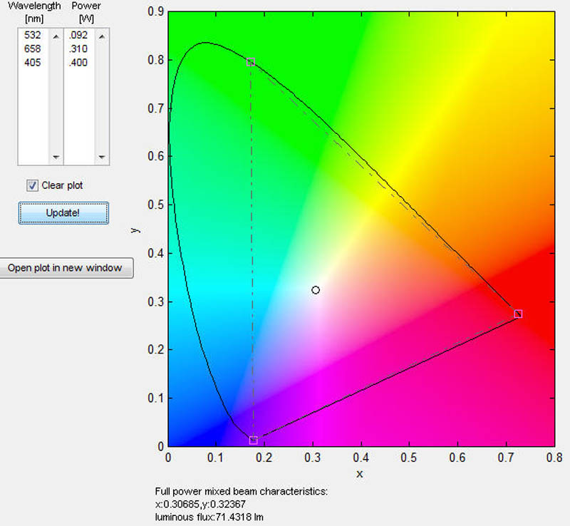
Update: I finally got Chroma to work on my PC This is a great program to figure out what powers to use when blending lasers. Here are some graphs I have made based on the commonly available Blu-Ray diodes. The plot shows a circle on on the color you would get with the wavelength and power of lasers in the field at the upper left of the app. I tweaked the values to get a well balanced white.

6x BRD
174mW%20405%20White%20Chroma.jpg


8x BRD
270mW%20405%20White%20Chroma.jpg


12x BRD I believe I made a safe choice for 12x output with a continuous duty cycle.
400mW%20405%20White%20Chroma.jpg
 
@Benm: You're right, but it seems strange to me.
Wikipedia, at the Laser Video Projector page, says "A rapidly rotating polygonal mirror gives the laser beam the horizontal refresh modulation. It reflects off of a curved mirror onto a galvanometer-mounted mirror which provides the vertical refresh."
That "rapidly" is the key? 160k rpm are waaaay too much.
Do you think I have to ask some optic store to make a custom made 150 or so sides polygon? The rotation value will drop at 6250 RPM, easier to reach.

@pullbangdead: my goal is to have a satisfying image, so I don't need to be so much precise. I think I will take the triangle from the input signal and apply with opamps a transformation in order to reach the basic RGV triangle, looking for a satisfying white point :)


mmh, this project seems to be more difficult (and expensive) than expected :D
 
Last edited:
I suppose that a polygon mirror with a large number of facets is part of the solution. I dont know the exact practical number, but the order of 10.000 rpm would not be any problem for a small scanning system.

They probably place this fast spinning mirror near the waist of the beam in some optical setup, so that it can be very small.
 
theres 1 other option to combining the colors.
if all you want to achieve is a liquid sky effect that can change colors all you need to do is shine all 3 lasers at the rotating mirror and line them up so the beams superimpose each other. i used this technique on my full color driver setup before it broke.
-nick
 
This seems like a pretty dead thread, but I was aiming to do the exact same project earlier this summer, but I haven't had any good luck with my green laser module (to be honest it might just be because it's a piece of crap I got out of a $5.29 Ebay greenie), and really doubt its ability to be modulated at a fast rate. The White Fusion kits/drivers modulate at a pretty low rate, maybe in the low kHz, however fast an LM317 can go, but I notice my green laser takes a little while to actually produce green light, like if I tap the switch really fast I'll see the red glow of the 808nm pump diode, yet no green photons. So would it be right to assume trying to modulate a standard green laser module at VGA resolution would be close to impossible? I found an article about how one of those pico projectors works, and they use a different crystal set, not the KTP we find in cheap pointers/modules.

I was planning on using a polygonal mirror as well though, I have 2 from a pair of broken laser printers, a 4 sided and 5 sided one. For the vertical deflection I was thinking of using a stepper motor, but I'm not sure if I can modulate that fast enough to get a 10-30 frame/s refresh rate. The other option would be to use something like a hard drive voice coil, but you would have to mess around with correcting the amplitude/position since I don't think it's linear.


Back
Top