Hello Everyone,
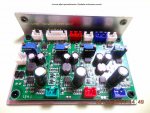
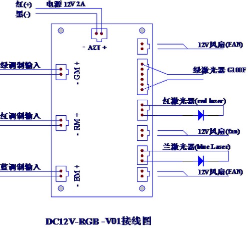
I recently bought this driver off ebay. I was wondering if someone knows this driver more ''in depth'' to tell me what the pinout is of the green laser connector.
The driver I am talking about is sold by Techhood.
Analogue RGB Laser Driver for 638nm 300mW 532nm 200mW 450nm 500mW Set 12V 2A | eBay
I have asked Techhood about this driver but he couldn't give me a proper explanation.
It's been a long time since I posted something on this forum. I hope this doesn't give me a negative reputation.


") will continue tinkering with it tomorrow.
will continue tinkering with it tomorrow.
 . I tried a few fans and there is a notable difference between the fans. The heating element connection switches off when the fan turns on. This is what I expected because it would be impractical to leave the heating element on whilst the fan is trying to cool it down (endless circle).