hi
i made my homemade laser and want to change the power supply to two cr123a batteries
that would be 6Volts because they will be rechargables
i will use a pot to reduce the current but if i want the voltage to be at around say 3 volts, would just using the pot work
SO it would be
6V-3=3
3V/300ma=0.01k or 10 ohms resistor/pot
So would that be safe,
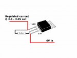
also i would rather do this than the lm117 coz it seems complicated and takes space
thanks
i made my homemade laser and want to change the power supply to two cr123a batteries
that would be 6Volts because they will be rechargables
i will use a pot to reduce the current but if i want the voltage to be at around say 3 volts, would just using the pot work
SO it would be
6V-3=3
3V/300ma=0.01k or 10 ohms resistor/pot
So would that be safe,
also i would rather do this than the lm117 coz it seems complicated and takes space
thanks


") )
)