
Welcome to Laser Pointer Forums - discuss green laser pointers, blue laser pointers, and all types of lasers
How to Register on LPF | LPF Donations

Navigation
Install the app
How to install the app on iOS
Follow along with the video below to see how to install our site as a web app on your home screen.
Note: This feature may not be available in some browsers.
More options
You are using an out of date browser. It may not display this or other websites correctly.
You should upgrade or use an alternative browser.
You should upgrade or use an alternative browser.
Red DIY DVD laser burner.
- Thread starter Kenom
- Start date


I'm thinking of getting one of these:
http://www.dealextreme.com/details.dx/sku.3329 (it actually uses a cr123)
Has anyone used this FL before for a laser mod. What do you think?
http://www.dealextreme.com/details.dx/sku.3329 (it actually uses a cr123)
Has anyone used this FL before for a laser mod. What do you think?
")

Gazoo
0
- Joined
- Jun 9, 2007
- Messages
- 3,206
- Points
- 38
It will have an infrared diode and won't do squat. If you get it out and working do not look into it, the dot will not appear bright, but is probably capable of damaging your eyes.
- Joined
- Aug 17, 2007
- Messages
- 238
- Points
- 0
Hey Ken:Kenom said:not bad at all. I'm glad that someone was able to use the flashlight as a good host. having it's own circuit inside was kinda handy and adding the extra circuitry is just going to make it last all teh longer.
Nice Job!
It sounds as though you're not too pleased with the Dorcy circuit anymore. Have you given up on it?
- Joined
- Aug 17, 2007
- Messages
- 238
- Points
- 0
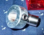
I was at Ace hardware looking for something to help dissipate the LD's heat and found this. It's called a shaft collar and has a nice set screw to tighten against the axizs module. It's made from aluminum which is a great material for heat transfer. It's a tiny bit sloppy but that can be filled in with thermal adhesive I assume. Only $2.55. Not bad if it works. It's larger than the inside diameter of the Dorcy head so it will have to protrude outside. I'll let you know how it works out.
Attachments
Kenom
0
- Joined
- May 4, 2007
- Messages
- 5,628
- Points
- 63
Hey Ken:photongeek said:[quote author=Kenom link=1181635652/225#238 date=1191725594]not bad at all. I'm glad that someone was able to use the flashlight as a good host. having it's own circuit inside was kinda handy and adding the extra circuitry is just going to make it last all teh longer.
Nice Job!
It sounds as though you're not too pleased with the Dorcy circuit anymore. Have you given up on it? [/quote]
No I’ve not given up on the dorcy jr completely. As we all know from the many projects and the datasheet from the gb diode. The current to go with to keep your diode alive and kicking for a good long time is somewhere in the 200-250ma range. Now the dorcy circuit is putting out 350-400ma. That spells certain doom for these diodes if you don’t add some additional resistors. Especially if you get the 400ma driver. I’ve toasted a total of 6 diodes trying to get them to work in dorcy jrs before I figured out the current was so high. So I havn’t completely given up on the dorcy Jr. but I certainly am not going to be using them anymore without some modification to the driver itself. I like the Dorcy slim 2AA focusable sold at sears. You do have to replace the circuit completely but I think it looks nicer.
photongeek said:I was at Ace hardware looking for something to help dissipate the LD's heat and found this. It's called a shaft collar and has a nice set screw to tighten against the axizs module. It's made from aluminum which is a great material for heat transfer. It's a tiny bit sloppy but that can be filled in with thermal adhesive I assume. Only $2.55. Not bad if it works. It's larger than the inside diameter of the Dorcy head so it will have to protrude outside. I'll let you know how it works out.
Yeah. Steve texas reported about shaft collars a long time ago saying that it was a lot easier than filling the head of the dorcy with solder. If I remember correctly it’s what he’s using in his metal gear mod. I’ve even got one that is very close in size to what I needed but mine is steel. Another idea for those that want a heatsink of some kind is drill stops. They are built the same way.
- Joined
- Sep 22, 2007
- Messages
- 169
- Points
- 18
why doesn't someone just sticky this thread? I think it's helpful to a lot of people and it constantly gets replies anyway.
- Joined
- Aug 17, 2007
- Messages
- 238
- Points
- 0
Sorry about your 6 dead LD's Ken. That blows big time!
I'm still going to try the original circuit but will definately cut the current with resistors. I also was able to get the 47uf tantalum caps very cheap on ebay since Radio Shack didn't have anything close.
You're absolutely right about using drill stops! I didn't think of those at all. The shaft collar was just a lucky find as I hadn't seen Steve's posting.
Kenom
0
- Joined
- May 4, 2007
- Messages
- 5,628
- Points
- 63
Actually it was stickied but there were so many sticky's that Daedal cleaned everything up by putting it in a group sticky. Threads of interest. This was the first of many stickies in this section and I was proud to wear that title for a long time. Then, everyone started posting such good information like daedals circuit and the others that the list was getting entirely too long. So good bye stickies. and now if you get the honor your thread gets added to the one sticky.
I'm actually playing with the idea of putting some resistors in as well. That and the capacitor. Only problem is, since I like to use the connectors on the bottom of the "light board" I don't have much room at all to install things like capacitors or resistors. That and my radio shack doesn't have the 5 ohm resistors Senkat told me to get. and since I'm essentially electronically illiterate I've no idea how to figure out how many or what resistor needs to get put in the circuit to bring the current down 10-50ma. Will a pot work?
photongeek said:Sorry about your 6 dead LD's Ken. That blows big time!
I'm still going to try the original circuit but will definately cut the current with resistors. I also was able to get the 47uf tantalum caps very cheap on ebay since Radio Shack didn't have anything close.
You're absolutely right about using drill stops! I didn't think of those at all. The shaft collar was just a lucky find as I hadn't seen Steve's posting.
I'm actually playing with the idea of putting some resistors in as well. That and the capacitor. Only problem is, since I like to use the connectors on the bottom of the "light board" I don't have much room at all to install things like capacitors or resistors. That and my radio shack doesn't have the 5 ohm resistors Senkat told me to get. and since I'm essentially electronically illiterate I've no idea how to figure out how many or what resistor needs to get put in the circuit to bring the current down 10-50ma. Will a pot work?
- Joined
- Sep 6, 2007
- Messages
- 51
- Points
- 0
Hey Ken, I'm pretty electronically illiterate too, but I got some 15, 22, and 33 ohm resistors at Radio Shack if you don't want to buy them from somewhere else and pay shipping. You can then reduce them by putting them in parallel and using this formula:
1/R[sub]1[/sub] + 1/R[sub]2[/sub] = 1/R[sub]T[/sub]
You can add more, just make R[sub]3[/sub] etc.
Basically, if you add x resistors of the same value in parallel, just divide the value by x (e.g., two 15 ohm resistors in parallel = 7.5 ohms, three 33 ohm resistors = 11 ohms.)
Mixing varied value resistors gets complicated (e.g., a 15 and a 33 ohm resistor would be 1/15+1/33 = 33/495+15/495 = 48/495 = 1/R -> R = 495/48 = 10.3125 ohms - fun, huh?) I can't help you out with what value you would need to knock down the mAs, but I'm sure someone else could easily help you out. I've really been wondering what kind of resistor to put in there too. And I gotta get my hands on some tantalum caps to fit in the module too... Anyhow, I hope that helped a little.
- Joined
- Aug 17, 2007
- Messages
- 238
- Points
- 0
Kenom said:Actually it was stickied but there were so many sticky's that Daedal cleaned everything up by putting it in a group sticky. Threads of interest. This was the first of many stickies in this section and I was proud to wear that title for a long time. Then, everyone started posting such good information like daedals circuit and the others that the list was getting entirely too long. So good bye stickies. and now if you get the honor your thread gets added to the one sticky.
[quote author=photongeek link=1181635652/240#249 date=1192147603]Sorry about your 6 dead LD's Ken. That blows big time!
I'm still going to try the original circuit but will definately cut the current with resistors. I also was able to get the 47uf tantalum caps very cheap on ebay since Radio Shack didn't have anything close.
You're absolutely right about using drill stops! I didn't think of those at all. The shaft collar was just a lucky find as I hadn't seen Steve's posting.
I'm actually playing with the idea of putting some resistors in as well. That and the capacitor. Only problem is, since I like to use the connectors on the bottom of the "light board" I don't have much room at all to install things like capacitors or resistors. That and my radio shack doesn't have the 5 ohm resistors Senkat told me to get. and since I'm essentially electronically illiterate I've no idea how to figure out how many or what resistor needs to get put in the circuit to bring the current down 10-50ma. Will a pot work?[/quote]
Here are some resistor combinations.
Attachments
:'( Hi Kenom, thanks for the instructions, now got some problems...
I keep killing my diodes!!! :-/ I'm currently using axiz 200mw diodes, and I don't know what I'm doing wrong...
I followed your instructions to the letter... I'm having some difficulty solding the wires from standard diodes to the diode's wires due to the fact that they are so close together (a few millimeters)
Secondly, when you say to 'bend' the wires, I don't know if this is killing my diodes, as any bending of the original could and usually kills the diode.
Attaching a heatsink is impossible due to the distance between wires, so I tried an aligator clip, but that seemed to bend the original wires...
Secondly, i used a 25w soldering iron, and tried to be as quick as possible,
it still heated the diode up very quickly, so I tried soldering with a 8w battery operated soldering iron to try and reduce the heat transfer...
also, when you mention to 'tap' the diode into the housing, i don't know how hard one has to tap, as I find the diode is quite difficult to 'tap' into the housing... (I also used some artic silver thermal grease too)
Finally, I ensured that none of the connectors were touching the housing, and all the wiring on the dorcy was isolated to positive and negative...
and each time I power up the diode, the output is fainter than a 1mw laser, then died completely on the second powerup :'(
So far I've gone though 2 diodes, and at $50Aus each, its becomming a rather expensive excercise... Any help would be greatly appreciated...
Thanks
Kenom
0
- Joined
- May 4, 2007
- Messages
- 5,628
- Points
- 63
tetrion said::'( Hi Kenom, thanks for the instructions, now got some problems...
I keep killing my diodes!!! :-/ I'm currently using axiz 200mw diodes, and I don't know what I'm doing wrong...
I followed your instructions to the letter... I'm having some difficulty solding the wires from standard diodes to the diode's wires due to the fact that they are so close together (a few millimeters)
Secondly, when you say to 'bend' the wires, I don't know if this is killing my diodes, as any bending of the original could and usually kills the diode.
Attaching a heatsink is impossible due to the distance between wires, so I tried an aligator clip, but that seemed to bend the original wires...
Secondly, i used a 25w soldering iron, and tried to be as quick as possible,
it still heated the diode up very quickly, so I tried soldering with a 8w battery operated soldering iron to try and reduce the heat transfer...
also, when you mention to 'tap' the diode into the housing, i don't know how hard one has to tap, as I find the diode is quite difficult to 'tap' into the housing... (I also used some artic silver thermal grease too)
Finally, I ensured that none of the connectors were touching the housing, and all the wiring on the dorcy was isolated to positive and negative...
and each time I power up the diode, the output is fainter than a 1mw laser, then died completely on the second powerup :'(
So far I've gone though 2 diodes, and at $50Aus each, its becomming a rather expensive excercise... Any help would be greatly appreciated...
Thanks
You have a lot of questions there that are very good. 1. I use a 75watt soldering iron. It gets very hot so that I don't need to keep the heat on the diode for very long.
2. for installing the diode into the module I now follow senkats instructions here: http://www.laserpointerforums.com/forums/YaBB.pl?num=1190209066;start=all
I don't actually bend the pins on the diode itself. I attatch pins from an led to the pins on the laser diode and bend the pins from the led about 1/4 above the pins. this makes it so there is no stress to the pins on the laser diode. I then solder those pins to the board and cut off any excess. It takes a bit of patience and skill to solder those wires to the diode pins. I do make sure I tin both the laser diode pins and the pins from the normal led BEFORE I try soldering the two together.
3. The dorcy circuit is now puttin out too much power for most diodes. 350ma-390ma is more than enough to kill the diodes. Try putting some resistors on the diode and a capacitor on the diode to reduce the current to 250ma-300ma. 250ma is safer. I'm not sure about the Aixiz diodes but I know that the diodes from the Group buy from senkat are rated at 250ma. it would be safe to assume the aixiz diodes are the same. to be honest I didn't know Aixiz sold just the diodes. I have only seen the diodes already mounted in a module. If you would like cheaper diodes you can buy the one's from senkat here. http://www.laserpointerforums.com/forums/YaBB.pl?num=1189708669;start=all
Hope this answers any questions you may have. I know that recently I've toasted quite a few diodes myself with the current coming from the Dorcy host and I'm having to add resistors and capacitors to my diode to save them from instant death. Hence the really really long picture of resistors and what they add up to post above yours.
Gazoo
0
- Joined
- Jun 9, 2007
- Messages
- 3,206
- Points
- 38
Kenom...you missed it. I do not recommend buying the diode from Aixiz...wait for the phasor diode test results and possible group buy.
http://www.laserpointerforums.com/forums/YaBB.pl?num=1189903200
http://www.laserpointerforums.com/forums/YaBB.pl?num=1189903200