

- Joined
- Feb 26, 2017
- Messages
- 6
- Points
- 0
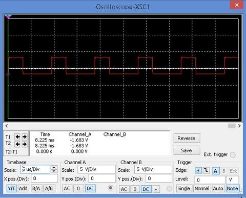
My first is question is this a normal waveform for TTL PWM?
If it is a bad waveform. Hear is the over all waveform. Over a stretch of time.
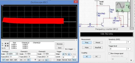
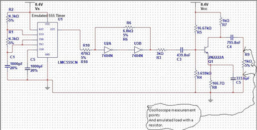
And is the transistor being over driven? In this next
schematic. If that is the case. Please tell me what components to change. And what frequency can you run. Red laser diodes from cd/dvd burnners.
Hear is a pluss to my question. I researtched the schematic 200mw dx green diode pumped solid state laser DPSSL 808nm infrared ir laser diode driver greeny. Tell me what you think please.
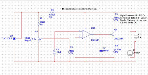
And as for the transistor 2N2222A. Is supposed to be 2SD882. The curcuit simulation software. Didn't have the part 2SD882. And C1 cap is tantalum electrolytic capacitor 10uF 16V. As for C2 is a 100 nf 12v ceramic capacitor. As for R6 it is simulated dummy load. The positive side of laser diode. Go's toward the transistor. That's it.
And all the parts you can get from Digikey. That's all happy lasing be save and smart peace.:beer:

If it is a bad waveform. Hear is the over all waveform. Over a stretch of time.

And is the transistor being over driven? In this next
schematic. If that is the case. Please tell me what components to change. And what frequency can you run. Red laser diodes from cd/dvd burnners.

Hear is a pluss to my question. I researtched the schematic 200mw dx green diode pumped solid state laser DPSSL 808nm infrared ir laser diode driver greeny. Tell me what you think please.

And as for the transistor 2N2222A. Is supposed to be 2SD882. The curcuit simulation software. Didn't have the part 2SD882. And C1 cap is tantalum electrolytic capacitor 10uF 16V. As for C2 is a 100 nf 12v ceramic capacitor. As for R6 it is simulated dummy load. The positive side of laser diode. Go's toward the transistor. That's it.
And all the parts you can get from Digikey. That's all happy lasing be save and smart peace.:beer:
Last edited:


 op:
op:
")