Welcome to Laser Pointer Forums - discuss green laser pointers, blue laser pointers, and all types of lasers

LPF Donation via Stripe | LPF Donation - Other Methods

Links below open in new window

ArcticMyst Security by Avery

"Protect Your Home with Laserbeams!" help

Comidt

0
Joined
May 31, 2007
Messages
285
Points
0
Hello all
Well, i live in South Africa, and as I'm sure many of you know, we have quite a bit of crime going on.
So... I was looking around for some kind of outdoor security thingy and came accoss this:
http://www.instructables.com/id/SYTR52PFD80BUX9/?ALLSTEPS

It is perfect. Just gonna build the things without mirrors, mount them on some poles cemented in the ground and then have my own laser trip wire. (Might use greenies though for extra coolness).

I noticed in the video that only when the beam is broken does the alarm go off. This wont help if someone runs through it really fast and it only goes off for 10ms... It has to make enough noise to wake me up so that I have time to get my laser and pepperball gun so that I am prepared for the baddies.

FHEWL9TFD80BUXE.MEDIUM.jpg

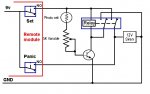
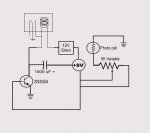
^ here is the circuit ^

So I need some electronics boffin to edit this circuit diagram to, when the beam is broken, trigger the siren, but then it must either stay on until I turn it off, or it must stay on for say, 10 seconds (maybe 30).

If anyone could kindly help me out with this, you will probably end up saving my life (literally).
Thanks very much

Oh, and also, maybe a way to have remote controlled on/off switch RF or something I guess.

Thank you all very kindly :)
Jonno


Joined
Jul 24, 2007
Messages
2,749
Points
0
TBH I cannot see how that circuit  is meant to work, what is the +9v thingy with 3 wires for instance????
I am not at my home computer at the moment but when I can i will draw you up a latching relay circuit that will keep the alarm on until you cancel it.

Regards rog8811
 
Joined
Jun 13, 2007
Messages
5,410
Points
113
I'm not sure if Turtlecannon is a member here, but if he is trying PMing him about this, he modified the circuit so the alarm would stay on until it was reset.
 
Joined
Jan 20, 2008
Messages
1,724
Points
0
the "9v" in the circuit is the positive terminal of the 9v battery. any of the gnd symbols are the negative terminal of the battery. it's a sloppy circuit diagram but it looks like it would work.

anyways, couldn't you just stick a relay in there so once it's triggered it stays on?
then you could add a normally closed pushbutton between the relay and gnd that breaks the circuit when pressed, as a way to turn it off.

something like this? (please excuse my crude mspaint relay, I'm in a hurry)
 

Attachments

  • FHEWL9TFD80BUXE_MEDIUM.jpg
    FHEWL9TFD80BUXE_MEDIUM.jpg
    19.8 KB · Views: 848
Joined
Jul 24, 2007
Messages
2,749
Points
0
it's a sloppy circuit diagram
It sure is.... I couldn't work it out until I saw your explanation :)

You have saved me from having to do a drawing as well.....just the NC push button needs adding as stated.

Regards rog8811
 
Joined
Jan 20, 2008
Messages
1,724
Points
0
rog8811 said:
it's a sloppy circuit diagram
It sure is.... I couldn't work it out until I saw your explanation :)

You have saved me from having to do a drawing as well.....just the NC push button needs adding as stated.

Regards rog8811

oh, heh, I didn't see above where you suggested a relay, I thought I was being clever :p

great minds think alike I guess.. ;D
 

Comidt

0
Joined
May 31, 2007
Messages
285
Points
0
Thanks very much guys ;)
So that will turn the alarm on until it is turned off?
What kind of relay would I need? (I'm a complete electronics un-understander, although I wish I took some course in it).
And a normally closed I can just get whatever right? Then when that is pressed, it deactivates the alarm?

Thanks all
Jonno
 
Joined
Jan 20, 2008
Messages
1,724
Points
0
Comidt said:
Thanks very much guys ;)
So that will turn the alarm on until it is turned off?
What kind of relay would I need? (I'm a complete electronics un-understander, although I wish I took some course in it).
And a normally closed I can just get whatever right? Then when that is pressed, it deactivates the alarm?

Thanks all
Jonno

Yep, that's the idea.

A relay is an electromagnet that pulls a switch closed when you give voltage to it. Relays are rated by how many volts it takes to trigger them. You'll probably want to use a 12v relay (which is incidentally the most common type.)

Here's a picture of one, they're really common in a lot of household electronic devices, especially any that "click" when they turn on. (I've found that broken coffee makers in particular are a great source of 12v relays)

Here is a picture of one:
12v-10a-relay.jpg


You can also run extra long wires for your siren and your disarm button, bury them under the ground and run them inside your house. That way only you can disarm it, and if you want you can hook more than one siren up to the same connections... but if you do that you may not want to use a 9v battery, it would be better to use a 9v adapter and use electricity from your house.

[edit]actually you probably want to use voltage from your house anyways, since I don't know how long a 9v battery could power a siren and a relay and the rest of the circuit... if you have a 9v adapter that says something at least as high as 500mA you should be able to run this circuit with a couple sirens comfortably.[/edit]
 

Comidt

0
Joined
May 31, 2007
Messages
285
Points
0
Thanks very much  :cool:
I was thinking of using this to remotely turn the system on/off.
http://electronics123.co.za/Main.as...8527-4AEF8A9D214C}&PageType=Product&SKU=FB917
Multitek Remote Control Receiver 1 Channel
This is a single channel receiver unit that
works with the Dyno keyring transmitters
(FB914), (FB915) and (FB916) to operate
devices over a maximum distance of 200m.
Ideal to operate electrical gates, doors and
alarm systems. It is programmed to a specific
channel by pressing a single on-board push
button. It can be set to latching or nonlatching
mode using a single on-board
jumper.
Specifications:
• Operating Voltage: 12Vdc
• Maximum Supply Current: 50m
• Operating Frequency: 403MHz
• Dimensions: 29 x 87 x 87mm
Product Code: FB917
Manufactured By: Multitek

And then this as a remote:
http://electronics123.co.za/Main.as...B482-27B5E41BD227}&PageType=Product&SKU=FB914

Dyno Remote Control
Transmitter
1 Channel 200m
This single channel Dyno keyring transmitter
is used with the Multitek Remote Control
Receivers (FB917), (FB918) and (FB919).
The code is set by means of a single 9-way
DIP switch.
Specifications:
• Supply Voltage: 12V alkaline battery (23A)
(DB247) (battery is included)
• Maximum Supply Current: 12mA
• Operating Frequency: 403MHz
• Transmission Range: 200m
• Dimensions: 14.5 x 37 x 82.5mm
Product Code: FB914
Manufactured By: Dyno
Would that work?

What if I got a 2 channel system and then one of the buttons could trigger the alarm, like a panic button?

Thanks very much again  ;)
 
Joined
Jul 24, 2007
Messages
2,749
Points
0
I use a similar 8 channel one of those to control zoom focus pan and tilt on a CCTV camera in my garden, they work fine :).
You just had to program it to tell it whether you wanted momentary or latched, it was a button on the receiver board if I remember correctly.

Regards rog8811

[edit]If I were to read the spec I would see that it says the above anyway...... so the only words on this post that means anything ....... they work fine ;) [/edit]
 

Comidt

0
Joined
May 31, 2007
Messages
285
Points
0
Ok, great thanks.

So when a Relay is switched on, it stays on until when?
How do you turn it off? I don't exactly understand.
If any of you have time, could you draw it up that's more undersandable for a noob like me?

Thanks very much
Jonno
 
Joined
Jul 24, 2007
Messages
2,749
Points
0
If you use the 2 channel remote both channels will be latching, (you cannot have one of each)  am redrawing that circuit....it is wrong.... watch this space..

Regards rog8811
 

Comidt

0
Joined
May 31, 2007
Messages
285
Points
0
Ok, thanks a lot Rog

Another Idea:

Universal Start / Stop Timer
catalogue.jpg

This is a compact timer kit with one start and
one stop push-button switch. It also has an
adjustable time delay between 1 second and
15 minutes. The output relay is switched on
and the time delay is started simultaneously
by pressing the start push-button. After the
preset time delay has expired the relay will
switch off. The relay can be switched off at
any time by pressing the stop push-button.
Specifications:
Supply Voltage: 12Vdc
Supply Current:
relay off: 20mA
relay on: 55mA
Adjustable Time Delay: 0 - 15 minutes
LED Indicator: shines while the relay is on
Output Relay Switch: SPDT, with COM., NO.
and NC. contact connections
Relay Contact Rating: 2A / 240V max.
PCB Dimensions: 38 x 69mm
Kit Product Code: GC094
Manufactured By: Velleman
Manufacturer Reference: K2579

I want to use this to run the siren for x seconds/minutes.
The start button is just a momentary switch, so I should be able to switch it with a relay right?
It is a kit, so I can modify it.
Then for the Remote, the relay from the receiver can just activate the reset switch.
Would that work?

I'm sorry if I'm asking too many questions, I'm just keen to build a nice security system.

What I'm thinking of doing know, is instead of builing multiple modules, I'm gonna get a more powerful laser from DX and run mirrors around the house and garden. Should work as long as i line up the mirrors well.

Thanks again
 
Joined
Jul 24, 2007
Messages
2,749
Points
0
OK, I think this is correct, I was not 100% sure which way the base of the transistor should go, I am sure someone will let me know if it is wrong :).

Regards rog8811

[edit]I have just seen your latest post, I need to think about that.....it will work..... I will get back to it tomorrow....my brain hurts ::)[/edit]
 

Attachments

  • remote_alarm01.jpg
    remote_alarm01.jpg
    72 KB · Views: 940

Comidt

0
Joined
May 31, 2007
Messages
285
Points
0
Ok, thanks Rog.
It is a lot more understandable now. ;)

I'm just trying to think how this whole thing works.
Is it that the more light falls on the cell, the more resistance it has or less?

What resistance Photo cell should I get?


Top