Welcome to Laser Pointer Forums - discuss green laser pointers, blue laser pointers, and all types of lasers

LPF Donation via Stripe | LPF Donation - Other Methods

Links below open in new window

ArcticMyst Security by Avery

Proper wiring for DIY 9v Ophir power supply?

Joined
Sep 22, 2010
Messages
1,358
Points
48
Since the ARG meter will be unavailable for the foreseeable near future and the new Delta line is out of my price range right now I've decided to go with the two 9v batteries and my DMM method until I can either get the funds for one or I get something else with data logging.

If I'm looking at the pic in SBA's thread it looks like I need to wire it up this way.

1. Common ground between the positive from the first battery to the negative from the second
2. Ophir's red wire (+v) to the positive on the second battery
3. Ophir's yellow wire (-v)to first battery's negative
4. Ophir brown wire (+ output) going to + voltage on my DMM
5. Ophir's orange wire (- output) going to common on the DMM.
6. DMM common linked to the common ground between the batteries.

DMM set to voltage.

If that's not right please let me know so I don't ruin my sensor.

Thanks!


ARG

0
Joined
Feb 27, 2011
Messages
6,772
Points
113
1. Yup
2. Yup
3. Yup (The wire is black typically)
4. Brown is GND on the Ophir head, goes to common on the DMM
5. Orange is signal, goes to + voltage on the DMM

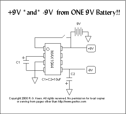
Could also just use a charge pump IC to power it from one 9V, such as this.
voltpmp2.gif
 
Joined
Aug 7, 2010
Messages
2,086
Points
0
With small effort, you can build a 9+9 PSU for your ophir. It could look kinda professional and AC mains powered.
A ebay Step-up driver is an option, too. ;)
 
Joined
Sep 22, 2010
Messages
1,358
Points
48
Thanks. I went by what I could see in that pic in the mentioned thread and the labels on the wires that the seller left. The red and yellow are labeled +/- 15V respectively so I knew where they went. The brown has a "T" on it which I thought was supposed to be a + and the orange I thought sad GND but now that I look closer I can't tell what it says.

I also see after buying a used head there's a bunch of new ones on fleabay for the same $225 I paid for this one. Oh well.


I'll wire it up tonight after my batteries charge and hopefully report back a success.
 
Joined
Jun 22, 2011
Messages
2,431
Points
83
An ebay step-up is probably not OK. There have been cases of noisy converters messing up the Ophir heads. I wouldn't risk unless someone else has already verified that particular converter is fine.

I'm currently powering mine from USB. An Arduino (with USB protection diode bypassed to avoid voltage drop) feeds a 5-15V DC/DC converter (previously verified to be fine by ARG) which goes through two 10V linear regulators (LM7810 and LM7910) and then to the Ophir.

My wire colors are different...
Black: -9V (batt1-)
Brown: GND (tap between batt1+ and batt2- and also connect to DMM-)
Red: +9V (batt2+)
Orange: DMM+
 

Trevor

0
Joined
Jul 17, 2009
Messages
4,386
Points
113
An ebay step-up is probably not OK. There have been cases of noisy converters messing up the Ophir heads. I wouldn't risk unless someone else has already verified that particular converter is fine.

Huh... I've never heard of that case (plural?). Did a member here report that?

Trevor
 
Joined
Jun 22, 2011
Messages
2,431
Points
83
There were multiple cases of problems with the Kenometer because of the DC converter if I remember correctly. I've seen other posts talking about this as well while I was reading about powering my Ophir but I'm not really sure how bad the problem was or how many got affected...
 

Trevor

0
Joined
Jul 17, 2009
Messages
4,386
Points
113
I thought that might be what you meant.

The ripple in the DC/DC converters caused the output reading to be noisy, but according to Jerry's test stayed within the specifications of the sensor and wouldn't have caused damage. That being said, if your supply is ripple-free, you get the best possible results from the head. But according to the datasheet and Jerry's test, it won't actually cause damage.

A few filter capacitors would have gone a long way toward making the Kenometers better...

Trevor
 
Joined
Jun 22, 2011
Messages
2,431
Points
83
Good to know. I was scared to death of powering mine after reading all that stuff, LOL!
 
Joined
Aug 7, 2010
Messages
2,086
Points
0
I agree with Trevor. Anyways, I didn't mean a Step-up converter alone would suffice.
You need a 9+9, not only a boosted voltage. You would need to build extra circuitry, including noise reduction on the power lines (dunno how to say that in english :thinking), etc.
 
Joined
Aug 7, 2010
Messages
2,086
Points
0
Anyways for those skeptical with filter capacitors resolving the booster problem, one could regulate the boosted voltage afterwards. A linear regulator should have good ripple rejection ;)

3.7V li-ion >boost> 24v >linear> 18v >converter; symmetrical from single supply> 9+9V

One with a o-scope could check the boost driver ripple and maybe don't use a linear regulator. I don't really know the ripple on those, its just a bet ;)
 

ARG

0
Joined
Feb 27, 2011
Messages
6,772
Points
113
When using those 15V converters I just use a 7812/7912 regulator in front. Add some decoupling capacitors and you have a clean supply.


Top