Welcome to Laser Pointer Forums - discuss green laser pointers, blue laser pointers, and all types of lasers

Buy Site Supporter Role (remove some ads) | LPF Donations

Links below open in new window

FrozenGate by Avery

problems with microboost


Sorry man. I'm at a relatives for Christmas. I only have my phone. I will look at it in a few hours when I get home.
 
here u r
(wires to LD are soldered temporary, because they go to test load. later I'll solder other wires, going to LD)
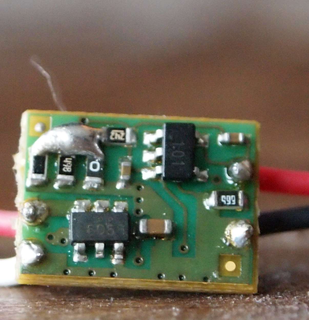

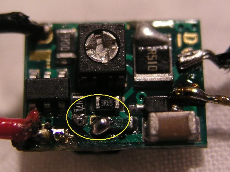
Jumpers look right, but I can see that the board got really hot in that second picture. Not sure if that may have caused one of the components to lose it's connection or something...

The third picture shows your negative input connected also to the near by resistor (or component), but that trace is going to that solder point anyway, so I don't see that as an issue...

Which is why I'm guessing something maybe got fried. (overheated maybe)

But yes, use a '4 silicon diode' test load for these. Not a 6. (unless it is for a low setting. Like 400mA's or less)
 
Last edited:
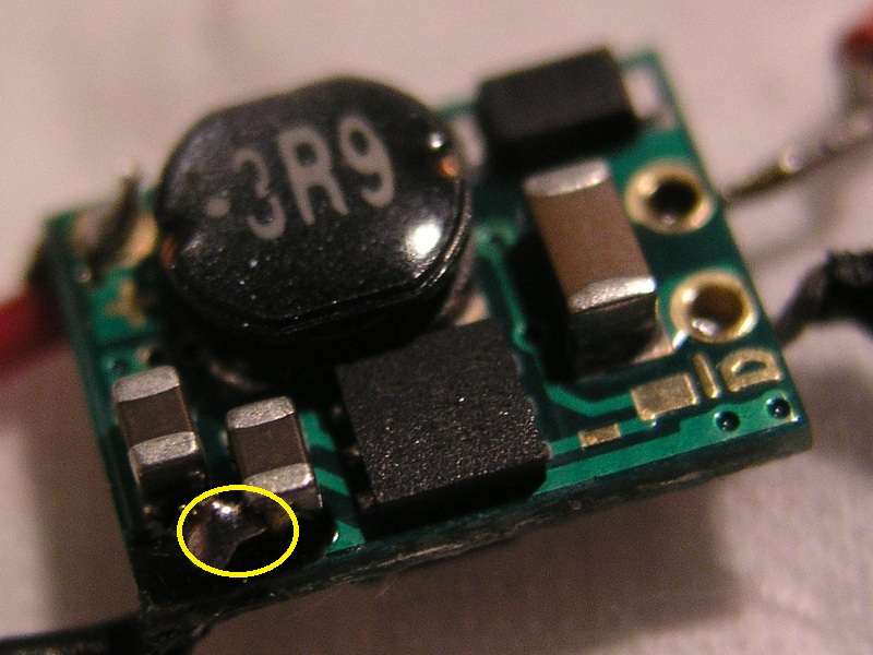
It is hard to tell for sure but it looks like you may have bridged these connections. Circled in yellow.

19808078.jpg


EDIT looks like Jay beat me to it.;) EDIT


Also for a real clean look and solid connection I like to strip the wires only to the depth of the hole and add a little flux to the top of the wire only. Then stick them through the hole and put a little solder on the top for a second or two and it will draw it in for a nice clean solid connection. This is a flex but same idea.;)

15956917.jpg


fd1v.jpg
 
Last edited:
Good pics. That's why I asked for them. I'm glad a couple of vets could chime in and offer their opinions. :beer:

As been said, the jumpers look correct except for your that your negative input is bridged to that resistor. But has Jayrob said, that resistor trace is going to that solder point anyway.

I would offer 2 pieces of advice:

1)PM your pics to the drlava himself and see what he says. I know he is busy and might not get back to you for a day or two but it's worth a shot. If anyone can tell you it would be him.

I thought I messed up the current jumpers on a flexdrive once (resistors fell off and everything) but I emailed drlava the pics and to my surprise he told me the important ones were still there and what to do to fix it so it was usable. Unfortunately I messed it up worse but thats not the point. :crackup:

2) In your OP you said you were setting the microboost to the highest setting of 540mA to 1000mA. There is actually a higher setting than that, 560mA - 1200mA. It's up to you but you could set it there by connecting all three resistors.

P1010831m.jpg
 
The inadvertently jumper-ed capacitors are fine. The last part of the microboost manual (Soldering Precautions) says so.

Those aren't resistors, by the way!
 
try charging your battery I have heard some of the flex drives "whistle" when they cannot get the current required.
 
There was one member that had a whistler, apparently it is still working for him.
Electrical components are usually pretty uniform in quality but there are always some discrepancies.


Back
Top