3zuli
0
- Joined
- May 30, 2009
- Messages
- 810
- Points
- 28
bump...


Follow along with the video below to see how to install our site as a web app on your home screen.
Note: This feature may not be available in some browsers.


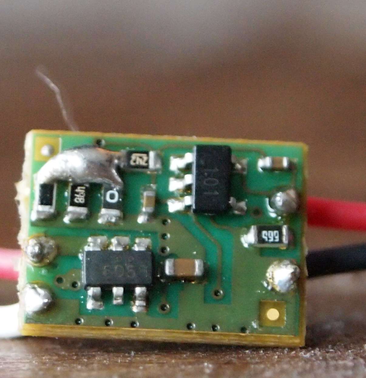
here u r
(wires to LD are soldered temporary, because they go to test load. later I'll solder other wires, going to LD)
")
") EDIT
EDIT