Welcome to Laser Pointer Forums - discuss green laser pointers, blue laser pointers, and all types of lasers

Buy Site Supporter Role (remove some ads) | LPF Donations

Links below open in new window

FrozenGate by Avery

Power Supply for a 15W CO2 Laser?

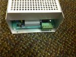
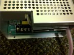
The power supply just got here! :D Excited to test out the tube but I don't know the pinout and it didn't come with a manual. Pictures of the front and back are attached, I sent a email to LightObject asking for a diagram erlier this evning, but encase they don't get back to me soon- do any of you guys have an idea of the pinout, or how this power supply is adjustable?
 

Attachments

  • front.jpg
    front.jpg
    395.2 KB · Views: 298
  • back.jpg
    back.jpg
    356.8 KB · Views: 402


It should be something like this...it seems that those power supplies have a common interface. H is TTL level active high input enable. when you put 5V there, it fires the laser. 0 stops it. L is the opposite. You can use a switch between L and G (GND). when the switch is closed, it lases.
WP is water pump sense intput. if you have some means of detecting water pump operation or water presence, you can use WP to disable/enable operation. if not, connect this input to G. IN is input for power control. it will accept 0-5V analog or TTL level PWM. You can connect it to the wiper of a 5-10k pot. 5V is 5VDC output (10-30mA max, i guess)
 

Attachments

  • iner.PNG
    iner.PNG
    76.3 KB · Views: 77,208
Thanks, what about the back four and the wire? Would I be correct in assuming the wire is my HV output and should be conected to the anode on my tube?
 
FG is ground terminal of your power cable, AC/AC is where Line and Neutral go. The fat red wire is the HV + output, should be connected to the anode of the tube. There must be a return terminal for the cathode as well.
 
Ok, so the far right pin (on the back) should be my HV return then, correct?
 
I don't know. The return of the power brick that i have is a slug bolted on the chassis. it seems also electrically connected to the chassis, FG,G...
 
Gotcha... Is there a way to test the pins without trying to find a voltmeter that will go up to 200KV?
 
Do you have your co2 tube yet? You need to test it under load. You could try drawing some long arcs, but i would strongly advise against that.
Take a regular multimeter and probe the two pins (FG and pin X) around the two AC pins for continuity to chassis ground. The FG pin is normally tied directly to it.
 
Found it! The fourth pin is the return. My tube's here but I'm out of town for the next few days and I'm still waiting on some other components (namely the water cooling system). Hopefully I'll get it runing next week
 
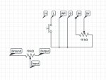
Just making sure, this is the proper wireing correct? The diagram posted erlier had the pot's ground connected to the 5V, the input going to the IN and the output going to the G. Also, nothing goes to or from the H, correct?
I've got everything else set up, once I'm done with this I'll be ready to testfire :)
 

Attachments

  • circuit.jpg
    circuit.jpg
    34.6 KB · Views: 2,564
ok, suppose you wire the pot like you have... what would happen when the wiper is close to ground?? answer: the 5v source is shorted. i have wired the pot on mine as per the diagram i posted earlier. the rest of the diagram is ok, i suppose you can leave H floating.
 
Yes, change it so the wiper of the pot goes to IN, and each end of the pot goes between 5V and GND.
 
ok, suppose you wire the pot like you have... what would happen when the wiper is close to ground?? answer: the 5v source is shorted. i have wired the pot on mine as per the diagram i posted earlier. the rest of the diagram is ok, i suppose you can leave H floating.

Ah, right!

Yes, change it so the wiper of the pot goes to IN, and each end of the pot goes between 5V and GND.

Still sending the pot ground to GND right?
 
Pots per se have no inputs, outputs and ground. wiper goes to IN, one end to 5, the other end to G. The wiper is usually connected to the center prong of the pot. You can of course swap the ends. doing so will change the min/max position.

hurry up because we want pictures :).

PS: Be extremely careful and dont apply power before anode and cathode are both securely hooked to the tube. the high voltage side may contain bleeder resistors, but even so, it will hold some shocking charge briefly even after the tube is off.
 
I just wired it up as Phenol's original diagram had, I'm using a 10K pot and it's only giving me a max of ~3kohms. As I rotate, it gets up to 3k, then goes back down to zero. Is this what should be happening?


Back
Top