Welcome to Laser Pointer Forums - discuss green laser pointers, blue laser pointers, and all types of lasers

LPF Donation via Stripe | LPF Donation - Other Methods

Links below open in new window

ArcticMyst Security by Avery

Please Help with my Dummy Load design (SOLVED. Pics and write-up!)

nabzim

New member
Joined
Oct 14, 2020
Messages
28
Points
3
I am trying to simulate an M140 diode, and I would like to run it at exactly 1.8A.
(The driver I'm using can supply up to 5A, so I fear the possibility of accidentally over-currenting my diode.)

For Test/Dummy Load:
Rectifiers: I will be using 10A10, because I have a ton of them already. (I have plenty of 1n4007 too, however unsuitable at this current.)​
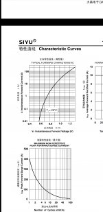
Forward voltage drop @ 1.8A = 0.8V (according to datasheet figure)​
Current-Sense Resistor: I will use a 2x2 Series-Parallel arrangement of 4x 1 Ohm, 1W metal-film resistors, which will have an equivalent resistance of 1 Ohm. (Using 1W because it's just what I have on-hand already.) This new resistor is rated for 4W, but will be dissipating 3.24W @ 1.8A.​

NOW HERE'S MY ACTUAL QUESTION/PROBLEM:
I have looked at various threads regarding this already, and have concluded that the voltage drop for the M140 diode is "somewhere around 4.5V"...​
Looked at several threads on test loads, and I have seen that diagram that everybody here uses as a reference.​
However, I'm still not sure how many diodes to use, so I did some calculations for test loads between 4 to 6 diodes.​
If I use 4 diodes in series, @ 1.8A, they total up to 3.2V drop.​
If I use 5 diodes in series, @ 1.8A, they total up to 4.0V drop.​
If I use 6 diodes in series, @ 1.8A, they total up to 4.8V drop.​
When I add in the 1.8V drop from the 1 Ohm resistor, I get:
The 4 diode test load @ 1.8A will have a total voltage-drop of 5.0V.
The 5 diode test load @ 1.8A will have a total voltage-drop of 5.8V.
The 6 diode test load @ 1.8A will have a total voltage-drop of 6.6V.

SO... I am slightly conflicted on how many diodes to put in series.
It seems like I should only use 4 diodes in series. Yay or Nay?
Thank you for your input.


gazer101

Well-known member
Joined
Feb 23, 2020
Messages
700
Points
63
Looking at a different datasheet I also see that the Vf would be just under 0.8V at 1.8A:
Screenshot_20201128-152813_Drive.jpg

So your conclusion seems fair but you should still test it out by providing 1.8A and measuring the Vf yourself
 

nabzim

New member
Joined
Oct 14, 2020
Messages
28
Points
3
So your conclusion seems fair but you should still test it out by providing 1.8A and measuring the Vf yourself
Thank you! That's a great idea, I will try this first.

BUT... I want to be totally certain, was I correct to sum the voltage drop of the resistor with that of the diodes?
Assuming 0.8V per diode is the truth, is a total drop of 5V a good approximation of the laser diode for testing-purposes? (and for accurately setting the current output?)
 

gazer101

Well-known member
Joined
Feb 23, 2020
Messages
700
Points
63
I'm not particularly good electronics wise, but when I make dummy loads I just assume that 2 diodes in series = 2 x Vf.
I think adding up the Vfs is fine
 

gazer101

Well-known member
Joined
Feb 23, 2020
Messages
700
Points
63
Yeah you also need to factor in your resistor (the actual load part of the dummy load) and how much it will drop the voltage if at all
 

nabzim

New member
Joined
Oct 14, 2020
Messages
28
Points
3
@gazer101 @Encap
Thanks, you guys!
You both gave information which I found very helpful, and from that I was able to test my driver, set the current, and therefore finish my laser! I will create a separate thread for pics of the final product.
But first, I'd like to share some pics of my dummy-load and the process of setting the driver current.

FYI:
The Laser Diode I am using (simulating) is an M140 (445 nm, 2W).
The driver I'm using (testing) is an Astral SuperDrive V. It can supply up to 5A, but I need to limit it to 1.8 A for the M140.
Luckily, this also means I won't need any heatsink on the driver's IC chip.

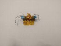
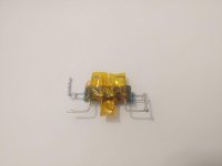
Here is my dummy load (4x 10A10 diodes, 4x 1W 1Ohm resistors) & Kapton tape... for insulation, and structural rigidity.
20201203_115943.jpg20201203_120014.jpg

Here is testing the dummy load (before testing the driver with it) using a constant-current to ensure that the predicted voltage-drop was correct:
20201128_214049_reduced.jpg almost there...
20201128_214111_HDR.jpg Viola! Spot-on!!!
I also probed the voltage across the resistor here, to make sure that my DMM and my bench supply both agree with each other:
20201128_214207_HDR.jpg
Looked okay-enough...
(Wish I had a Fluke meter instead... 🙄)

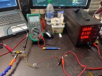
Then I soldered leads to the driver and the dummy load, and stripped wires to clip on test-leads. DMM probes go across the resistor.
I set the bench supply to 8.4 V (constant V mode) to simulate fully-charged batteries (2x 18650's in series, 2*(4.2 V) ).
The potentiometer was already pretty close to where I had wanted it:
20201128_221852_HDR.jpg
A little adjustment:
20201128_222258_HDR.jpgThat's good-enough for me! Done!

Then, out of curiosity, I wanted to see the current at a "fully discharged" battery voltage... (3.2 V per cell is the lowest I want to allow), so at 6.4 V (at driver-input):
20201128_222024_HDR.jpg 1.6 A with "low battery".

This indicates that the driver does not supply a prefect "constant current", however I believe that claim is in reference to a variable load-voltage, not a variable supply-voltage!
Makes sense, because the load (laser diode) is what needs to be protected from over-current, and not necessarily the supply. (Although some protection for the supply is a great idea!)

Then, I thought, I may as well see the current at the "nominal cell voltage" (also the same V as "storage voltage" for lithium cells) 3.7 V per cell:
20201128_222114_HDR.jpgStill almost the same 1.6 A!

So, we can assume the driver will retain a mostly-constant-current, over "some range" of input voltages!

It would be a great idea to do this same test again, and record the current over the entire battery-voltage-range, while taking many more measurements at evenly-spaced intervals (maybe, say, 0.1 V intervals).

Then, I could create an accurate plot of how the current (supplied to the diode) changes over the course of the battery discharge cycle!

Hopefully I'll get around to that sometime... but, as of this moment, I'M TOO LAZY! 😆

Thanks again for all the help!
I will create a separate thread about my laser, and after it's up, I'll post a link to it in this thread!
 

nabzim

New member
Joined
Oct 14, 2020
Messages
28
Points
3
Posted it!
Here:
laserpointerforums.com/threads/my-very-first-laser-build-445nm-2w-m140-my-alternative-laser-host-and-analysis-of-build-cost.107706/


Top