

- Joined
- Sep 22, 2010
- Messages
- 1,360
- Points
- 48
Since it had been a couple months since I built a laser I decided it was time to do something with a PHR diode that's been sitting on my desk since I pressed it in October.
Update: I've added some more pictures in the next post and answered a couple questions I've received. Also for some reason some of my pictures are randomly not showing up even though i haven't modified anything on Flickr. If you click on them they will open to their page on flickr.
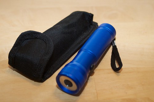
2011-01-15_05-24-08pm by ltkernelpanic, on Flickr
Hotlights host from Mohrenburg. Nice smaller host but still has a beefy heatsink and comes with a carry case.
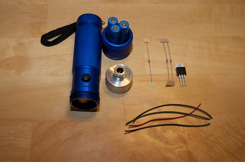
2011-01-15_06-15-09pm by ltkernelpanic, on Flickr
Parts list:
Hotlights host kit (includes some of FP's awesome wire)
10 ohm 1/4w resistor
5.1 ohm 1/8 resistors
LM317T voltage regulator used as a current regulator
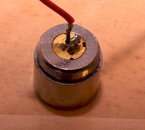
PHR-803T pressed into an Aixiz module with standard acrylic lens
3x 10440 LiIon rechargeable batteries
Not shown is the 3xAAA battery holder inside the host. If you decide to use 10440s DO NOT get the protected ones. They will not fit!

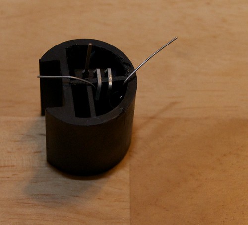
2011-01-15_07-05-42pm by ltkernelpanic, on Flickr
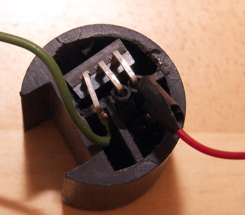
Like the Guidesman hosts you can easily remove one of the ribs from the pill/spacer to make room for your driver. I cut as far down as I could with a razor blade then used needle nose pliers to pull the soft plastic out.
2011-01-15_08-07-23pm by ltkernelpanic, on Flickr
Test fitting the LM317 after its output and adjust legs were bent to fit . Also test fitting the resistor package after soldering the two 5 ohm resistors in parallel which was then soldered to the 10 ohm in series for a total of ~12.5 ohms. (the 5ohm were actually 5.1 ohm. I ordered the wrong part for a previous build and deiced to use up a few)

2011-01-15_08-07-55pm by ltkernelpanic, on Flickr
The resistor package on top of the LM317 before soldering. At my target current of 100ma the resistors need to be able to withstand about .13w which my 1/8w resistors in parallel should handle fine but to be safe I attached the 1/4w to the output leg when I made the final joints.

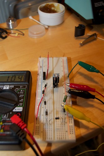
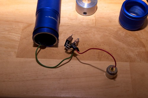
2011-01-15_09-24-28pm by ltkernelpanic, on Flickr
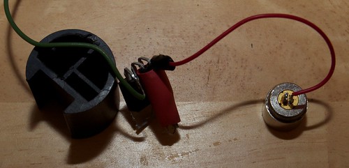
Double checking everything before soldering on the batt + and LD+ leads.
2011-01-15_09-25-05pm by ltkernelpanic, on Flickr
Another shot showing the completed driver.
I didn't take any pictures of the final assembly but all that was left to do was bend the input leg to fit into the smaller left cavity of the pill, shrink the heat shrink tubing and attach the leads from the host and to the diode. o prevent any shorts I put a piece of electrical tape over the top of the plastic pill to keep it from shorting against the bottom of the positive battery contact. I also put a piece over the top of the positive battery contact to prevent it from shorting to the bottom of the heatsink. One thing I forgot to do initially was solder a bridge between the case pin and LD- to complete the ground. One of the left over resistor leg trimmings worked perfectly for that.
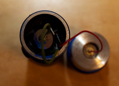
2011-01-16_10-41-55pm by ltkernelpanic, on Flickr
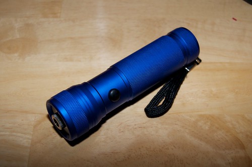
The completed laser.
2011-01-16_10-44-16pm by ltkernelpanic, on Flickr

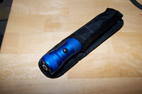
2011-01-16_10-44-43pm by ltkernelpanic, on Flickr
Nice and snug!
Beam shots! I really need to get a fog machine. The beam is a very nice deep violet even though it looks kind of blue in the pics.
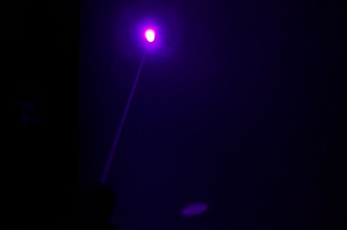
2011-01-16_10-22-30pm by ltkernelpanic, on Flickr
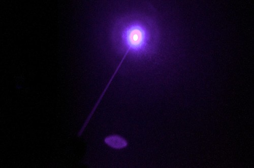
2011-01-16_10-21-24pm by ltkernelpanic, on Flickr
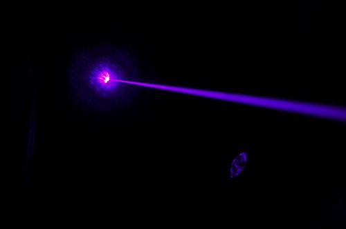
2011-01-16_10-29-11pm by ltkernelpanic, on Flickr
LPM testing.
Two minute LPM test.

Screen shot 2011-01-17 at 12.05.31 AM by ltkernelpanic, on Flickr
Even though it says 89mw I'd say it's actually 87 because that's what I measured it at after I finished the build. I suspect my LPM was picking up some heat from my heater because after turning the laser off it was bouncing from 1-2mw. Finally to answer the inevitable questions - yes it burns and lights regular red matches almost instantly. I don't have any balloons handy and they tend to startle the dog.
This project was pretty cheap to complete wouldn't be too bad as a beginner's build. Not counting consumables it used only about $35 (plus S&H) in parts not including batteries and charger. If you'd rather not harvest and press your own diode add another $5-10 to the final cost. The planning took a couple hours but the build time itself was less than an hour and was pretty easy if you have the right tools and some soldering skills. Feel free to ask questions and I'll try to answer them the best I can.
Update: I've added some more pictures in the next post and answered a couple questions I've received. Also for some reason some of my pictures are randomly not showing up even though i haven't modified anything on Flickr. If you click on them they will open to their page on flickr.
2011-01-15_05-24-08pm by ltkernelpanic, on Flickr
Hotlights host from Mohrenburg. Nice smaller host but still has a beefy heatsink and comes with a carry case.
2011-01-15_06-15-09pm by ltkernelpanic, on Flickr
Parts list:
Hotlights host kit (includes some of FP's awesome wire)
10 ohm 1/4w resistor
5.1 ohm 1/8 resistors
LM317T voltage regulator used as a current regulator
PHR-803T pressed into an Aixiz module with standard acrylic lens
3x 10440 LiIon rechargeable batteries
Not shown is the 3xAAA battery holder inside the host. If you decide to use 10440s DO NOT get the protected ones. They will not fit!
2011-01-15_07-05-42pm by ltkernelpanic, on Flickr
Like the Guidesman hosts you can easily remove one of the ribs from the pill/spacer to make room for your driver. I cut as far down as I could with a razor blade then used needle nose pliers to pull the soft plastic out.
2011-01-15_08-07-23pm by ltkernelpanic, on Flickr
Test fitting the LM317 after its output and adjust legs were bent to fit . Also test fitting the resistor package after soldering the two 5 ohm resistors in parallel which was then soldered to the 10 ohm in series for a total of ~12.5 ohms. (the 5ohm were actually 5.1 ohm. I ordered the wrong part for a previous build and deiced to use up a few)
2011-01-15_08-07-55pm by ltkernelpanic, on Flickr
The resistor package on top of the LM317 before soldering. At my target current of 100ma the resistors need to be able to withstand about .13w which my 1/8w resistors in parallel should handle fine but to be safe I attached the 1/4w to the output leg when I made the final joints.
2011-01-15_09-24-28pm by ltkernelpanic, on Flickr
Double checking everything before soldering on the batt + and LD+ leads.
2011-01-15_09-25-05pm by ltkernelpanic, on Flickr
Another shot showing the completed driver.
I didn't take any pictures of the final assembly but all that was left to do was bend the input leg to fit into the smaller left cavity of the pill, shrink the heat shrink tubing and attach the leads from the host and to the diode. o prevent any shorts I put a piece of electrical tape over the top of the plastic pill to keep it from shorting against the bottom of the positive battery contact. I also put a piece over the top of the positive battery contact to prevent it from shorting to the bottom of the heatsink. One thing I forgot to do initially was solder a bridge between the case pin and LD- to complete the ground. One of the left over resistor leg trimmings worked perfectly for that.
2011-01-16_10-41-55pm by ltkernelpanic, on Flickr
The completed laser.
2011-01-16_10-44-16pm by ltkernelpanic, on Flickr
2011-01-16_10-44-43pm by ltkernelpanic, on Flickr
Nice and snug!
Beam shots! I really need to get a fog machine. The beam is a very nice deep violet even though it looks kind of blue in the pics.
2011-01-16_10-22-30pm by ltkernelpanic, on Flickr
2011-01-16_10-21-24pm by ltkernelpanic, on Flickr
2011-01-16_10-29-11pm by ltkernelpanic, on Flickr
LPM testing.
Two minute LPM test.
Screen shot 2011-01-17 at 12.05.31 AM by ltkernelpanic, on Flickr
Even though it says 89mw I'd say it's actually 87 because that's what I measured it at after I finished the build. I suspect my LPM was picking up some heat from my heater because after turning the laser off it was bouncing from 1-2mw. Finally to answer the inevitable questions - yes it burns and lights regular red matches almost instantly. I don't have any balloons handy and they tend to startle the dog.
This project was pretty cheap to complete wouldn't be too bad as a beginner's build. Not counting consumables it used only about $35 (plus S&H) in parts not including batteries and charger. If you'd rather not harvest and press your own diode add another $5-10 to the final cost. The planning took a couple hours but the build time itself was less than an hour and was pretty easy if you have the right tools and some soldering skills. Feel free to ask questions and I'll try to answer them the best I can.
Last edited:


 Some pictures are not working.
")