Welcome to Laser Pointer Forums - discuss green laser pointers, blue laser pointers, and all types of lasers

LPF Donation via Stripe | LPF Donation - Other Methods

Links below open in new window

ArcticMyst Security by Avery

Odicforce Boost Driver?

jnrpop

0
Joined
Dec 7, 2008
Messages
722
Points
63
Yeah if you are seeing only at the 1 Ohm resistor, then it's okay the V=I*R is of course applies :D

What i thought about resistance on the post above is an R generated from the Vt/I
where the Vt = diode's Vf + 1Ω.
but it seems the formula isn't as simple as that :crackup:

ah ok,
I believe that when we use a Testload, to set the output current, the only "resistance" we are using is the 1 Ohm resistor on the Testload. So that should stay constant.
Also its why we can measure across this resistor and using V=IxR, we convert the mV reading to mA. So then i though of course if we use a Testload, then the resistance doesn't change, therefore if the Vf changes, so must the Current. The Diodes are not linear that is correct, and you can see that in the above Graphs, also in your calculated graph in post #34 astralist.
In my graphs, the "measured" Vf that drops by ~0.7V is linear, but the resulting Current reading is non-linear, from the diodes, CMIIW
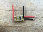
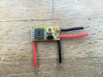
Edit:
Here's both sides of the driver from Odicforce, its different to the Pictures they use on thier website:

attachment.php

attachment.php
 

Attachments

  • ld1.jpg
    ld1.jpg
    229.5 KB · Views: 72
  • ld2.jpg
    ld2.jpg
    223.6 KB · Views: 85
Last edited:


Joined
Mar 27, 2011
Messages
504
Points
43
I see,

One other thing i forgot to mention,
sometimes i just omit the 1Ω resistor and replace it to a multimeter (ammeter), so the current will be measured directly without reading the voltage from 1Ω resistor.
I always thought that we use 1Ω resistor because voltmeter is readily available than a multimeter that can measure >5A continuously.

The actual laser diode are without 1Ω resistor right? :crackup:
so it should only be simulated with a series of diode IMO :D

And now, when the 1Ω is omitted, where is the "resistance" now? :D
 
Last edited:

jnrpop

0
Joined
Dec 7, 2008
Messages
722
Points
63
I see,

One other thing i forgot to mention,
sometimes i just omit the 1Ω resistor and replace it to a multimeter (ammeter), so the current will be measured directly without reading the voltage from 1Ω resistor.
I always thought that we use 1Ω resistor because voltmeter is readily available than a multimeter that can measure >5A continuously.

The actual laser diode are without 1Ω resistor right? :crackup:
so it should only be simulated with a series of diode IMO :D

And now, when the 1Ω is omitted, where is the "resistance" now? :D

Haha, yep exactly.

I thought the 1Ω resistor was necessary to generate a load for the drivers safety? If it wasn't there wouldn't the drivers output be short circuited with no load?

on second thought, i'm digging my hole deeper again. Sometimes electrical princibles are really hard to interpret.
 
Last edited:
Joined
Sep 20, 2013
Messages
17,252
Points
113
Guys, of course a diode is nonlinear. It drops 0.7 volts regardless of the current going through it. To be linear, the voltage drop would need to change with the current as it does with a resistor. Having a 1 ohm resistor in your series of diodes doesn't introduce enough of a difference to make the dummy load inaccurate. It you start out using 9 diodes in your series, then reduce the number to 6 diodes, the current should remain within a reasonably narrow range if the driver is regulating current properly. I have used this procedure to check every driver I've ever set up. In good drivers, the current will always stay within a narrow range if the driver is working properly. This boost driver is nothing more than a CV source as can be seen with the change in current with every diode removed from the series. Use it at your own peril.


Even omitting the resistor and using an ammeter doesn't remove the resistance from the load as the ammeter introduces its own resistance in order to measure current. This amount of resistance is negligible, as is the 1 ohm resistor, in this case.
 
Last edited:

honeyx

0
Joined
Jun 12, 2011
Messages
377
Points
28
This boost driver is nothing more than a CV source as can be seen with the change in current with every diode removed from the series. Use it at your own peril.

Exactly. If you want to make it a CC driver, you have to modify it the way i posted before. For e real CC driver the number of diodes doesn´t matter. Once the current is set, it will remain there. No matter there are 6 or 9 diodes. Just the voltage will differ. The 1 Ohm resistor is there as every DMM in Amp mode has a different internal resistance and therefore the results can differ from DMM to DMM. In Voltage mode they all do have a much higher resistance and therefore reading voltage insteed of current will result in much more accurate readings.

In this configuration this driver is nothing more than this
 
Last edited:

jnrpop

0
Joined
Dec 7, 2008
Messages
722
Points
63
Thanks for the input Paul, Honeyx, Astralist :beer:

I've got a much clearer idea on these drivers now. CC is CC and should remain CC. Like Astralist said before, the current can be constant with these CV drivers if the Vf drop doesnt change, but it does...with heat etc.
I'd still like to hook up a SXD,X-drive or nano and do the same tests ive done with these Odicforce drivers.

Edit: Have you got a link Honeyx, for the modification?
 
Last edited:
Joined
Sep 20, 2013
Messages
17,252
Points
113
I don't think the IC s the same as the one in Honeyx's diagram. The pins don't seem to match. The number on the IC is AL675, but I was unable to find a diagram for it anywhere. I could change this to a CC driver if I knew what that IC is.
 

honeyx

0
Joined
Jun 12, 2011
Messages
377
Points
28
I´m pretty sure it is a SX1308. Datasheet

The upper right pin is FB connected between R1&R2. The one below is GND and the one on the buttom is SW1. On the left you have EN and IN connected to Vin. The one on the buttom is NC. The Pot is connected through NC and further below the IC to the lead between R2 and R3.

Have no direct link to show how it should be modified on this driver. Just the shematics I posted before. You would have to remove all the resistors and connect a sense resistor between GND and the FB pin where FB acts as V- for the diode. A 1Ohm resistor would result in 600mA.

Just be warned. When you have done the modification, never run the driver without a Load, else it will kill the IC imediately.
 
Last edited:

jnrpop

0
Joined
Dec 7, 2008
Messages
722
Points
63
I don't think the IC s the same as the one in Honeyx's diagram. The pins don't seem to match. The number on the IC is AL675, but I was unable to find a diagram for it anywhere. I could change this to a CC driver if I knew what that IC is.

On the two drivers i have the IC number is AL531
 

honeyx

0
Joined
Jun 12, 2011
Messages
377
Points
28
The IC as a quite popular boost driver IC sold by many manufaturers under different names. Most known as SX1308 or MT3608. Having here several SX and MT driver modules and all chips do have a different number on it. If you are unsure, measure the leads and compare to the datasheet. The one i linked to is a top view of the chip. On some chips you will find a dot next to pin 1.
 
Joined
Sep 20, 2013
Messages
17,252
Points
113
Yes, you are telling me things I have known for years. There are some similarities to the SX1308, but I will have to do some more work to see if I can use it as a template to modify this one. The feedback pin is not necessarily the same on this IC. Will see what I can find out with some more research into this IC.
 

honeyx

0
Joined
Jun 12, 2011
Messages
377
Points
28
Yes, you are telling me things I have known for years. There are some similarities to the SX1308, but I will have to do some more work to see if I can use it as a template to modify this one. The feedback pin is not necessarily the same on this IC. Will see what I can find out with some more research into this IC.

This was not to you but to jnrpop. Hoever if you are having the driver, the better to reverse engeenier it. I´m just talking about what i can see on the pics. And the circuit looks exactly the same like a typical circuit for this IC exept the additional R3 resistor going from the voltage divider (R1,R2, Pot and R4) to Vin. Probably this resistor is the resaon why they say it has a soft start and a reverse polarity protection, though I can´t see any soft start behavior on the scope as well.

So well, if it turns out to be a SX1308 or a clone of it, this driver is not worth the money as a CV driver. You can get 10th of them for a few $$ on ebay and modify them to CC drivers.
 
Joined
Sep 20, 2013
Messages
17,252
Points
113
That is a good point, Honeyx. It might be a better option to modify those as apposed to trying to make this one work as stated in their descriptions.
 
Joined
Mar 27, 2011
Messages
504
Points
43
Just to clarify, it's not an SX1308 IC
Like I said before it's from feelingtech

And I thought you all already know.
Here is the model number:
FP6291

Package marking/identification of SOT-23-6:
ALXYY
Where AL = marking number of FP6291; X = year; YY = lot number/batch

And here is the datasheet:
>click here<
 
Last edited:
Joined
Sep 20, 2013
Messages
17,252
Points
113
I have looked over the data sheet and it could very well be what you say, astralist. The problem still exists that it is a voltage regulator in the configuration of this driver. The over current protection circuit won't regulate the current...... just shut it down when current sense "sees" more current than it is set for. As a driver in this circuit, it is useless. I can see making the FB pin tied to the cathode of the LD and from there to gnd through a low value resistor. This should make it act as a current regulator.....unless I am missing something.
 
Last edited:
Joined
Mar 27, 2011
Messages
504
Points
43
You start out using 9 diodes in your series, then reduce the number to 6 diodes, the current should remain within a reasonably narrow range if the driver is regulating current properly.
I have used this procedure to check every driver I've ever set up. In good drivers, the current will always stay within a narrow range if the driver is working properly.

Which specific driver did you use paul?
I've just tested an SXD driver which i just pull out from a working laser (NUBM07E), the result are just like what i said earlier:


Closed circuit ~5A @ 0V
1Ω 4.58A @ 4.58V
1Ω +1 Diode 3.79A @ 5.24V
1Ω +2 Diode 3.12A @ 5.41V
1Ω +3 Diode 2.43A @ 5.56V
1Ω +4 Diode 1.79A @ 5.71V
1Ω +5 Diode 1.27A @ 5.86V
1Ω +6 Diode 0.75A @ 5.98V
Open circuit 0A @ 6.69V

Real world current when connected to NUBM07E = ~4.5A

P.S:
This driver has been modified to deliver 5A Isc (I short circuit) as per calculation on paper,
because the original configuration i paid and i get from DTR are real 4.5A Isc (i buy a 4.5A SXD)
but when connected to NUBM07E only delivers ~3.5A.
just like i said earlier here


Would you still call this a current regulating driver?
It's been used by many people without problem.
BTW i'm not trying to bash anyone product,
just pure curiosity because all my designed driver are also behave that way when introduced to a set of diodes as load
. :confused::confused:
Also, next time my blackbuck 8M arrives, i'll also test it out. :)

I can see making the FB pin tied to the cathode of the LD and from there to gnd through a low value resistor. This should make it act as a current regulator.....unless I am missing something.

You are correct, that's what it takes to convert a buck/boost voltage regulator to a buck/boost current regulator
only, you might want to use some opamp/current sense IC to enable the use of small sense resistor.

But after all, the result are just what we see above.
IMHO if we want a real "constant current" driver, then a small 15mm * 10mm PCB are not enough due to the compensation added.
 
Last edited:


Top