Welcome to Laser Pointer Forums - discuss green laser pointers, blue laser pointers, and all types of lasers

LPF Donation via Stripe | LPF Donation - Other Methods

Links below open in new window

ArcticMyst Security by Avery

NUBM31T 95W 455nm

BrilliantLasers

Active member
Joined
Apr 11, 2019
Messages
122
Points
28
In this image, I think the plus and minus are reversed.
Positive is the side with the model number on it(NUBM31), in that picture it's difficult to tell for sure what side we are looking at. I quickly threw it together so I might have made a mistake.


toutan

0
Joined
Dec 1, 2010
Messages
202
Points
28
Positive is the side with the model number on it(NUBM31), in that picture it's difficult to tell for sure what side we are looking at. I quickly threw it together so I might have made a mistake.
Don't worry.
I checked on the internet.
 

toutan

0
Joined
Dec 1, 2010
Messages
202
Points
28
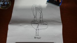
I came up with this wiring scheme.
It's a way to use two converters and connect them in parallel.
If I do it this way, can't I use a small 250W boost converter to light it up?
If I use one converter in series, I would need a higher voltage.
I thought this would work with a lower voltage.
What do you think?

DSC01209_result.JPG
 

BrilliantLasers

Active member
Joined
Apr 11, 2019
Messages
122
Points
28
I came up with this wiring scheme.
It's a way to use two converters and connect them in parallel.
If I do it this way, can't I use a small 250W boost converter to light it up?
If I use one converter in series, I would need a higher voltage.
I thought this would work with a lower voltage.
What do you think?

View attachment 72748

That should work, given the battery and converters can handle the high amp load. What is the max voltage of your boost converters?
 

toutan

0
Joined
Dec 1, 2010
Messages
202
Points
28
I think it will light up this way, but the problem is
How many settings should I set for the voltage and current?
 

BrilliantLasers

Active member
Joined
Apr 11, 2019
Messages
122
Points
28
I think it will light up this way, but the problem is
How many settings should I set for the voltage and current?
I'm no expert. But since you are in parallel, I believe the voltage should be around 20-22v. The current should be roughly 5-6 amps, and 7 amps if you have good cooling for the laser array. Speaking of cooling, what are you using for cooling your laser array? Do you have a good heat sync? I would recommend using a computer CPU heat sync. You cannot run that laser without a heat sync.
 

BrilliantLasers

Active member
Joined
Apr 11, 2019
Messages
122
Points
28
So I already explained this in my previous posts but here's a TLDR of why parallel is better for a multitude of reasons:
Due to the mentioned extreme output capacitance of the Chinese "drivers" If ANY laser dies in the array fail close suddenly all of the other dies will get overcurrented because the output cap will be charged at a bigger voltage that what they are collectively dropping leading to them all drawing a few dozen more amps in a very short pulse from the output cap than their nominal. As you can imagine quite a devastating scenario leading to the loss of the entire array.

If you have the array in parallel, in case of a failure all strings will effectively take the current that the die that died took leading to a marginal current increase among all of them which is much more survivable than the current loop failing altogether and ending up delivering a short but ultra-high current pulse. Also, it would be safer overall since you decrease the risk of electric shock from very possible to 0(24v vs 92v) and making a reliable lower voltage but higher current supply is much more easy and cost-effective than a low current high voltage one. (Forgot to add, The opamps typically used in said Chinese "drivers" are too slow to correct in time for the first mode of failure(series))

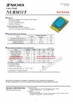
I wanted to point this out. This is why I was under the impression these ARE in fact supposed to be run in series. This is the spec sheet from Nichia. The voltage is calculated in series. Why would only series voltage be listed if it was intended to run in parallel like you claim? Am I missing something here?


nubm31specsheet.jpg
 

toutan

0
Joined
Dec 1, 2010
Messages
202
Points
28
I'm no expert. But since you are in parallel, I believe the voltage should be around 20-22v. The current should be roughly 5-6 amps, and 7 amps if you have good cooling for the laser array. Speaking of cooling, what are you using for cooling your laser array? Do you have a good heat sync? I would recommend using a computer CPU heat sync. You cannot run that laser without a heat sync.
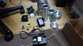
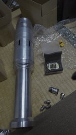
I have a host for 100W that I purchased from trinh.
I am going to use it to produce a 100W laser.
It has a large aluminum heat sink and an air cooling fan.
 

likevvii

Member
Joined
Mar 2, 2020
Messages
74
Points
18
I am not sure how this will affect things in the long run,
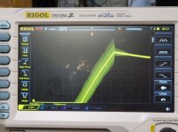
Here is a test when I connected the output side of a 1200W DC boost converter that is set to 1A constant current.
*The boost converter is already ON and resting at 48V input.
20210220_161554.jpg
As you can see here, even when set to 1A output, the voltage spikes to around 100V.

For an example, if it is set to 10A, it may overshoot to even higher voltages. I don't have a picture, but it got up to 128V when I was playing around at 5~6A if I remember correctly.

On another thing that could be tested is powering on the driver while the laser is already connected on the output. It may lead to even higher voltage spikes.

___
These DC boost converters would be perfect if they had slower ramp. Are there some resistors or capacitors we can swap to slow the voltage ramp so we don't have so much overshooting maybe?


People have been using DC boost converters for quite a long time and as far as I know, no one has has their diode array fail because of a DC boost converter. I'm beginning to think these high powered 450nm laser diodes are just as robust as high powered LEDs.
 

BrilliantLasers

Active member
Joined
Apr 11, 2019
Messages
122
Points
28
I am not sure how this will affect things in the long run,
Here is a test when I connected the output side of a 1200W DC boost converter that is set to 1A constant current.
*The boost converter is already ON and resting at 48V input.
View attachment 72766
As you can see here, even when set to 1A output, the voltage spikes to around 100V.

For an example, if it is set to 10A, it may overshoot to even higher voltages. I don't have a picture, but it got up to 128V when I was playing around at 5~6A if I remember correctly.

On another thing that could be tested is powering on the driver while the laser is already connected on the output. It may lead to even higher voltage spikes.

___
These DC boost converters would be perfect if they had slower ramp. Are there some resistors or capacitors we can swap to slow the voltage ramp so we don't have so much overshooting maybe?


People have been using DC boost converters for quite a long time and as far as I know, no one has has their diode array fail because of a DC boost converter. I'm beginning to think these high powered 450nm laser diodes are just as robust as high powered LEDs.

Well, the 600w one on Amazon max voltage is around 90v. Is it possible it's still peaking higher than its max voltage? Cause if it doesn't, wouldn't that mean it's perfectly safe since 90v would not be able to draw significant amperage? I mean, it can't be peaking much higher since it's capacitors I think are only rated for 100v.
 

BrilliantLasers

Active member
Joined
Apr 11, 2019
Messages
122
Points
28
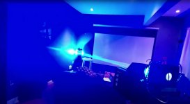
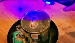
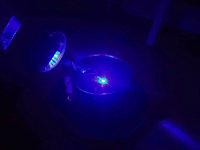
If anyone was wanting to see a compilation of some of the photos I've taken of my NUBM31 laser pistol, here they are!
LaserFPSJPG.jpgLaserMeltjpg.jpgBeamDayjpg.jpgBeamPointjpg.jpgmetaljpg.jpg

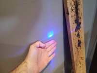
This shot here shows me experimenting with beam expansion(Low power test). Interesting shape it created from 15ft away.
Smalldot.jpg
 

toutan

0
Joined
Dec 1, 2010
Messages
202
Points
28
Are there any focusing lenses on Aliexpress or eBay that can be used with the NUBM31T?


Top