Welcome to Laser Pointer Forums - discuss green laser pointers, blue laser pointers, and all types of lasers

LPF Donation via Stripe | LPF Donation - Other Methods

Links below open in new window

ArcticMyst Security by Avery

New 3A Driver, Very Cheap

Joined
Aug 14, 2013
Messages
2,655
Points
63
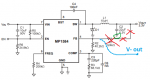
The original R3 is 100k and C3 is most likely 150pF. The optimal value for R3/C3 depends on the voltage
drop of the diode. For a 445, say 5V maybe? It also depends on the operating frequency and C2. So
let's say you use the original value for R4 which should give 911kHz if my math is right. In that case R3
should be 323k and C3 220pF. There is something wrong with the formula for C3, so based on the values
in table 3 I just divided either R3 or fc by 1000.


rhd

0
Joined
Dec 7, 2010
Messages
8,475
Points
0
Something just occurred to me -
The MAX4172 has a PGOOD output. What if that output was tied to the regulator's EN pin? Since the MAX4172 gets its operating power independently of the regulator output, it seems like this approach would get the MAX4172 up and running before current flows.

Sent from my Nexus 5 using Tapatalk
 
Joined
Aug 14, 2013
Messages
2,655
Points
63
Well yesterday I did some testing and I can say that it isn't going to be as simple as
unsoldering the pot and attaching a sense resistor to FB and ground. I manufactured a 0.57Ω
resistor out of some nichrome, which should yield an expected output of 0.8 / 0.57 = 1.4A. It
is oscillating between 800mA and 1.4A at around 130kHz. I'm not exactly sure how to
proceed, but I suspect it may have something to do with the compensation network. At least
it isn't overshooting.

attachment.php


It isn't the stray inductances and resistances of my test setup, either. I tried making more
direct connections and rolling up the wires, all to no effect.

attachment.php
attachment.php
 

Attachments

  • Cheap Driver 1.gif
    Cheap Driver 1.gif
    3.5 KB · Views: 1,624
  • Modified Driver.jpg
    Modified Driver.jpg
    122.1 KB · Views: 1,954
  • Test Setup.jpg
    Test Setup.jpg
    149.5 KB · Views: 1,707

rhd

0
Joined
Dec 7, 2010
Messages
8,475
Points
0
I think you would have to remove more than just one resistor (or pot). There's likely a resistor divider in the stock circuit, and you'd have to remove both sides of it.

Sent from my Nexus 5 using Tapatalk
 

rhd

0
Joined
Dec 7, 2010
Messages
8,475
Points
0
I had considered it, but the other resistor is in parallel with the new one and only contributes about 40µΩ.

I don't see how you could take a circuit that is configured for constant voltage via a resistor divider, remove one resistor, and have a constant current circuit. I just can't see that working in my head.

If you removed only the resistor between FB and GND, then you wouldn't have output current flowing over the remaining resistor (nor the sense resistor that you said is in parallel with it). Similarly, if you removed only the resistor between FB and V+ Out, then you'd have a resistor between FB and GND remaining, but you'd need to bring V- Out to the FB pin, so that current then flowed to GND, over the resistor.

In other words, it's not as simple as merely removing a single resistor. You basically need remove the portions marked in RED, create a trace or wire for V- Out as indicated in BLUE (this is not a GND feed anymore), and then likely attach the cap where circled in GREEN to V- Out, rather than to GND. In that setup, R2 becomes your sense resistor.

attachment.php
 

Attachments

  • example.png
    example.png
    27.3 KB · Views: 3,591
Last edited:
Joined
Aug 14, 2013
Messages
2,655
Points
63
I thought the modifications would be clear from the pictures, but since that is apparently not
the case, here they are are in schematic form. The resistor I added is in red. I really want to
get this to work, but have a cold the past couple days and don't feel like doing anything.

You'll notice I haven't touched the capacitor. That could be the whole problem. There are
some other switch mode drivers out there that have it connected as you suggested, the
Velleman K8071 not being among them. That one has similar problems, though for the life of
me I cannot figure out what difference this could possibly make. Maybe when I am feeling a
little better all things will become clear.

attachment.php
 

Attachments

  • 3A Laser Diode Driver.gif
    3A Laser Diode Driver.gif
    20 KB · Views: 2,642
Joined
Sep 12, 2007
Messages
9,399
Points
113
If the voltage at the feedback pin is also oscillating, add more capacitance to the output. 130kHz should be fairly easy to get rid of.
 

rhd

0
Joined
Dec 7, 2010
Messages
8,475
Points
0
This may be an obvious point, but did you use your own caps? I wouldn't be surprised if those boards from China, for that price, used underspec caps.

Sent from my Nexus 5 using Tapatalk
 
Joined
Aug 14, 2013
Messages
2,655
Points
63
Cyparagon said:
If the voltage at the feedback pin is also oscillating, add more capacitance to the output.
130kHz should be fairly easy to get rid of.

Indeed it was. Will give that a try :thanks:

rhd said:
This may be an obvious point, but did you use your own caps? I wouldn't be surprised if
those boards from China, for that price, used underspec caps.

attachment.php
attachment.php
 
Joined
May 25, 2013
Messages
534
Points
28
I have two 650 diodes out of dvd burners looking for a good drive and module to put them in im still new to laser builds worked for a electronic manufacture few years ago so I know how to solder I just looking for some thing to keep my mind sharp any help would be appreciated
You should really post this in a different section etc, your question is not very relevant to the OP, 3AMP is too much even for both of your diodes ! good luck anyway....
 
Joined
Aug 14, 2013
Messages
2,655
Points
63
Capacitors! Capacitors everywhere!

3A%20Driver%20Beamshot.jpg


Well, I'm finally confident enough to attach it to a LASER diode. It WANTS a capacitor from
output straight to ground, or else it is very unstable. The output current is now a nice straight
line across my oscilloscope. My homemade nichrome resistor gets very warm. :D

3A%20Laser%20Diode%20Driver.gif
3A%20Laser%20Diode%20Driver%20Modifications.jpg


Top