Welcome to Laser Pointer Forums - discuss green laser pointers, blue laser pointers, and all types of lasers

Buy Site Supporter Role (remove some ads) | LPF Donations

Links below open in new window

FrozenGate by Avery

Need to amplify this

To increase the voltage of the regulator, stick some power diodes in leg 2 to increase it with steps ov 0.7V.

Try injecting a voltage at IC pin 3 of the opamp (or disconnect the opto and put a 9V battery instead of the 4.7K) and see if it works then.

Measure the voltage at pin 2 and 6. When 2 is lower then 3, 6 should be Vdd, when 2 is higher than 3, 6 should be 0V.

That's all I can give you remotely.


I got it working now with a 9v regulator.

But it behaves just like the other setup, it doesn't really fade.

And I only get 3.4V out to the ddl driver.


I did ssome measurements ob the pins between GND:

With voltage added to the optoisolator I get 0V at pin 2, 1.47V at pin 3, and 6.9V at pin 6.

With no voltage added to the optoisolator I get 0V at pin 2, 0V at pin 3 (and the LED glows dim for some reason when the probe makes contact), and 0V at pin 6.
 
FireMyLaser said:
With voltage added to the optoisolator I get 0V at pin 2, 1.47V at pin 3, and 6.9V at pin 6.
That's the problem then. There voltages should be equal (and close to 0, so use a mV meter). With 1.47V at pin 3, there should flow 1.47A to the ddl driver. The reason the circuit is not saturating might be a too low supply voltage or a too high resistor between pin 9 and the darlington. When 1.47A is too high, increase the 180K resistor above the pot.
 
Zom-B said:
[quote author=FireMyLaser link=1214844611/24#33 date=1215691696]With voltage added to the optoisolator I get 0V at pin 2, 1.47V at pin 3, and 6.9V at pin 6.
That's the problem then. There voltages should be equal (and close to 0, so use a mV meter). With 1.47V at pin 3, there should flow 1.47A to the ddl driver. The reason the circuit is not saturating might be a too low supply voltage or a too high resistor between pin 9 and the darlington. When 1.47A is too high, increase the 180K resistor above the pot.[/quote]

I'm sorry but I don't understand that post, it's too confusing.

(It still doesn't work, please help)
 
Do you have a multimeter capabel of measuring mV (preferrably 0.1mV)?

What current does the DDL drivers need?

Do you have your 'oscilloscope' on your line-in working?

Then, know some basics of the design. An opamp is a differential amplifier. It amplifies the voltage between the input and output times a few million (clipped to the supply voltages). In other words (in this circuit) it outputs Vdd when pin 2 is lower than pin 3, and outputs Gnd when pin 2 is higher than pin 3. When the voltage on both pins is equal, the output floats somewhere in between to find a balance.

The output drives a transistor. This lets a current flow. This current also flows through the 1 Ohm resistor, creating a voltage relative to Gnd. This voltage is dependent on the drive for the transistor (but not entirely linear). Because this voltage is feed back to pin 2, the voltage on pin 2 is always equal to the current flowing through this resistor (and your DDL driver).

Combining these two situations, the situation exists where the voltage on pin 3 is always mimicked at pin 2. For that it has to have a current flowing through the resistor, for that it has to drive the transistor. In other words, the voltage given at pin 3 will drive the DDL with the same amount, but in mA.

So, when you want the DDL driver to accept X mA at maximum, and the optoisolator supplies Y Volts (probably close or equal to Vdd), then the voltage Y must be lowered to voltage X without loss of linearity. This is achieved with two resistors as a voltage divider (one is 180K plus the top part of the potmeter, and the other is the lower part of the potmeter). We assume the potmeter is in the middle ideally, and is turned only when calculations are off. The ratio of both resistors to the lower resistor is equal to ratio Y to X. The top resistor is then relative to Y-X. When the potmeter is 50K (for example) the lower part is 25K. When Y is nine times X, then the top part is (Y-X)/X = 8 times the lower part, so the top resistor should be 8x 25K = 200K. The real top resistor (without the other part of the 50K potmeter) is then 175K. (180K because 175K does not exist on the E24 scale) For other values, of X and Y this differs ofcourse. This is just an example.

Formal notation and simplified for ease of calculation:
Given:
- Rp = potmeter
- X = max DDL current, in Ampere (taken as Volts)
- Y = optoisolator voltage
Calculate:
- Rt = top resistor = ((Y/X-2)*Rp/2

Also do take a look at the specs of the optoisolator and change the 4.7K resistor to achieve the most effective.
 
I'm sorry for the late reply...

"Do you have a multimeter capabel of measuring mV (preferrably 0.1mV)?" -Yes

"Do you have your 'oscilloscope' on your line-in working?" -I think so (Rog helped me), but I don't know how to use it.

I want to be able to use whatever I need between 100-400 mA (what I set the ddl driver to) and 9-12V to power my lasers. I just want to be able plug them to the RGB circuit when I need to, and then take them out again for other uses.

In my 'mind' I see (and want) the amplifing circuit to be as relays, but of course much faster and solid state.  :) Simple as that really, but is this possible without tuning everything to the exact current?
 
In my 'mind' I see (and want) the amplifing circuit to be as relays, but of course much faster and solid state.

I have some solid state relays on order to try out, I will let you know if I can get them to work.... (I am aware that in the thread someone said they are probably not suitable...But I like to try things out ;) )

Regards rog8811
 
Sounds good Rog!


Should I quit? This doesn't go anywere and I can't get the darn thing to work. :( So far Rog's setup works the best so I guess that I'll use for now that untill something comes up...

<waiting>

PS, thanks for your help Zom-B! Feel free to post any advise you might have, or if you want me to continue. :)
 
I have to try every option before I quit...... for example I built a 2 channel signal generator to use as a dummy TTL input to see what frequency I can get to with the SSR's.......
If you go on with it and get it working you will have learnt a lot and will feel that satisfied glow that comes with success :)

Regards rog8811
 
maybe the optoisolators are the problem.
why have them anyway. i think you should go back to the original idea. but just have a FET (and transistor to drive it from the flashing circuit) then have a lm317 circuit for current limiting. keep it simple!

a low pass filter shouldn't be necessary, you should be able to PWM a laser and make it appear dimmer to our slow human eyes
 
woop said:
maybe the optoisolators are the problem.
why have them anyway. i think you should go back to the original idea. but just have a FET (and transistor to drive it from the flashing circuit) then have a lm317 circuit for current limiting. keep it simple!

a low pass filter shouldn't be necessary, you should be able to PWM a laser and make it appear dimmer to our slow human eyes
I like the way you think how I think. ;D

But how do I do it? What components do I need?


I'm not much of a electrical wizard... yet.
 
Please, don't make me go to another forum to get some answers. [smiley=engel017.gif]

I really want to make this.
 
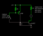
try this
oh and make that 100R resistor a 1K
 

Attachments

  • circuit.png
    circuit.png
    8.3 KB · Views: 261
Just a question, I hope you don't mind me asking in your thread.

Does a laser diode turn on and emit photons as quickly as a LED?
 
positron said:
Just a question, I hope you don't mind me asking in your thread.

Does a laser diode turn on and emit photons as quickly as a LED?

No problem. ;)
Yes. I belive they're capable of emitting millions of light pulses per second.


Thx Woop! How do I know if a componet is a N-FET? What do they look like? Also, the pulse is on the cathode and is about 3.5V.
 
so with your crazy flashing board, its active low right? so it connects the led to ground to turn it on?
thats what that circuit is made for

and fet's look like power transistors. go to your electronic shop and ask for a n channel power fet. it should look like this
z1853.jpg


you should be able to salvage one, sometimes the pins are labeled G, S, D on the pcb. and n-channel is the most common type of fet


Back
Top