Welcome to Laser Pointer Forums - discuss green laser pointers, blue laser pointers, and all types of lasers

LPF Donation via Stripe | LPF Donation - Other Methods

Links below open in new window

ArcticMyst Security by Avery

Need help with setting current on a Driver!

Joined
Dec 18, 2008
Messages
199
Points
18
I´m sorry I think ive overread this severval times o_O
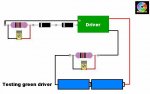
Yes its a green laser with a 808 pump diode that should be driven with 300mA...
At the test drive I am using the 1Ohm resistor you recomend at your drawing , thats all no more resistors used . I got the strange reading without any resistors between the input , and the 1ohm resistor of the TL.
I´ll add another diode now..

Regrads
game-genie


Joined
Jul 24, 2007
Messages
2,749
Points
0
Does your setup look like this? (shows 2 1N4001's.. you will now try 3)

EDIT...... as the OP is now sorted I will explain why the drawing shows two 1ohm resistors and multimeters

You can test the driver for a green with a test load of three 1N4001 diodes (not two as shown) and a 1ohm resistor before soldering to your laser diode. This will tell you whether the circuit is working.

Once you have removed the test load, Shorted the output solder pads with no power applied and added the laser diode, you can put a 1ohm resistor between the battery and the driver to check it is set to the required current.

Regards rog8811
 

Attachments

  • testing green driver.jpg
    testing green driver.jpg
    29.6 KB · Views: 168
Last edited:
Joined
Dec 18, 2008
Messages
199
Points
18
No it doesnt looks like this , there is no resistor in the input!

Anyway adding a 3rd diode helped i now get a reading when i measure the mV between the 1ohm resistor . It also gives me over 250mV ...

I think this Problem is solved! If ive another problem ill post it.
In german I would now say "Tausend Dank !" you were a really great help!

Best regards
game-genie

Edit: Just set the pot to 275mA and added my DPSS module - everything working perfect!
Thanky agein rog
 
Last edited:
Joined
Jul 24, 2007
Messages
2,749
Points
0
No it doesnt looks like this , there is no resistor in the input!

So when I wrote "Do you have another 1ohm resistor?
If so put it between the battery and the driver, doesn't matter if it is in the pos or neg line, now measure the mv across the resistor, what do you get"?
Did you try it or not? the reason I suggested it was as a diagnostic tool to check what is happening within the driver....

Sounds like the extra 1N4001 might do the trick anyway.
Regards rog8811
 
Joined
Mar 25, 2008
Messages
1,007
Points
38
Well, i too just broke my driver. Unfortunately, it was a little more complex of a driver (http://o-like.com/b2b_cpinfo.asp?id=966), so I hope these CC drivers you're talking about (which I also bought) will work.

Also, does anyone know, around what current would be good to set a 50-60mW module? Also, I planned on using TTL on this, so this driver supports TTL and should work fine, correct? If so... what's the point of having the big driver they use vs. this small driver?
 
Joined
Jul 24, 2007
Messages
2,749
Points
0
Also, does anyone know, around what current would be good to set a 50-60mW green module? Also, I planned on using TTL on this, so this driver supports TTL and should work fine, correct? If so... what's the point of having the big driver they use vs. this small driver?
Help us out, not everyone has the time to click links to find out......
I would guess that the range of the driver we have been discusssing will work fine with that module. As to the point of the large driver, they should be more robust and better regulated, I have had similar ones from DX and they were crap, as soon as you touched the pot they blew the LD....:(

Regards rog8811
 

Maxi3D

0
Joined
Jun 10, 2009
Messages
29
Points
0
Thanks you guys, This page has more info for a newbie like me than I could ever searched on google. Like they said, a picture is worth a thousand words, and the pictures of the test load circuits are priceless. Someone should make this post a sticky for the noods like me.

Edit: One finds mV across the resister to get mA is by ohm's law (V/R = I) am I correct? Thanks.
 
Last edited:


Top