Welcome to Laser Pointer Forums - discuss green laser pointers, blue laser pointers, and all types of lasers

LPF Donation via Stripe | LPF Donation - Other Methods

Links below open in new window

ArcticMyst Security by Avery

Nano SSTC!

Fiddy

0
Joined
May 22, 2011
Messages
2,726
Points
63
Hey Guise,

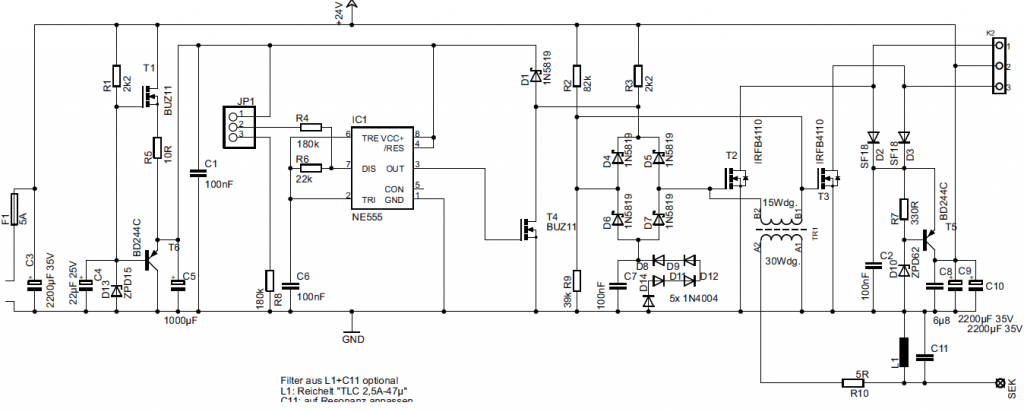
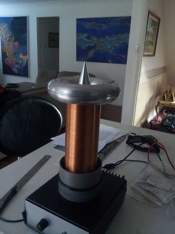
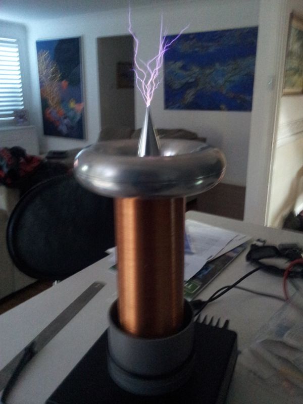
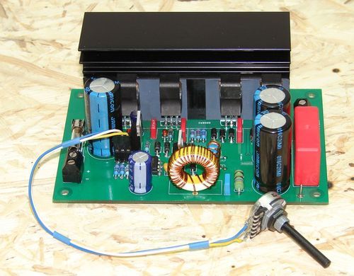
Heres a SSTC i bought off eBay a while ago,

It runs off 24VDC from a 5A wall supply.

sstc1.jpg


sstc2-1.jpg


It has a pot on the front to control the PRF only.

DriverBoard.jpg


It came with a smaller toroid, about 4" diameter and it didn't look real nice, ive installed a 6" spun toroid since and a break out spike, since ive changed the toroid im having trouble with the the power mosfets dying and the PRF control only fires when the PRF pot is wound up high.

I know the bigger toroid will lower the resonant frequency of the primary, so ive changed the capacitor on the PCB to lower the primary's resonant frequency to suit.

I have a scope to measure stuff, im not sure how to measure the resonant frequency of the secondary,

If you have some experience in the SSTC feild and have some suggestions id like to hear them!

Fiddy.


Joined
Jan 14, 2009
Messages
1,452
Points
83
Well the easiest way to measure secondary resonance is with a O-scop and function generator , there are othere ways but I haven't a clue on them :p

For my mini PLL SSTC I just swept though the frequency range on the PLL till I got the largest output possible , then the PLL takes care of the rest .

Nice Coil :D
 
Last edited:

Fiddy

0
Joined
May 22, 2011
Messages
2,726
Points
63
yeah, might need to get me a function generator, ive only got a scope.

ive got a PLL driven one but ive got a whine in the system that i cant seem to shake.
 
Joined
Jan 14, 2009
Messages
1,452
Points
83
yeah, might need to get me a function generator, ive only got a scope.

ive got a PLL driven one but ive got a whine in the system that i cant seem to shake.

You could use the PLL IC as a variable square wave source and use that to find the resonance with the O-Scope


What type of driver does the 24V coil use , im assuming its a normal SSTC , not DR type , changing a toroid on the secondary wont affect the primary resonance , only the secondary . Its weather the drivers range is within the new secondary resonance frequency ,

When you say there is a capacitor on the primary are you referring to the actual bridge or a capacitor for the controller , if the capacitor you changed was on the bridge its self guessing that its a full bridge driver looking at the picture that capacitor will just be a DC blocking cap and has not affect on the primary resonance on a normal SSTC ,
 
Last edited:

Fiddy

0
Joined
May 22, 2011
Messages
2,726
Points
63
interesting idea.

heres my schematic:

sstcschemtic.png


C11 is what i changed to change the primary resonance.
 
Last edited:
Joined
Jan 14, 2009
Messages
1,452
Points
83
interesting idea.

heres my schematic:

sstcschemtic.png


C11 is what i changed to change the primary resonance.

Well looking at that , On a wild guess id I have no idea how that runs xD , what connections does the primary connect to , if its connection K2 on pins 1 , 3 then I would say the inductor and C11 form a resonant circuit that then drives the GDT to drive the mosfet gates that drive the primary , with the 555 timer acting as the interrupter .

But then looking at it , does the sek pin go to the secondary base connection ?

It looks like a Push / pull setup on the primary . with pin 2 on connector K2 as the centre tap .

Sound about right ? or I could be miles off :p
 
Last edited:

Fiddy

0
Joined
May 22, 2011
Messages
2,726
Points
63
yeah k2 is the primary winding(s) its a tapped coil.

thats pretty close, why does the gate transformer attach to the secondary coil? for feedback?
 
Joined
Jan 14, 2009
Messages
1,452
Points
83
yeah k2 is the primary winding(s) its a tapped coil.

thats pretty close, why does the gate transformer attach to the secondary coil? for feedback?

It looks like that the Inductor / capacitor start the oscillations , then the secondary feedback takes over , or the secondary feedback is used to drive the inductor / capacitor oscillator to keep the oscillations going to drive the GDT
 
Last edited:

Fiddy

0
Joined
May 22, 2011
Messages
2,726
Points
63
yeah thats what i was thinking. i dont know what is causing it to only fire when the pot is wound right up/
 
Joined
Feb 1, 2008
Messages
2,894
Points
0
yeah, might need to get me a function generator, ive only got a scope.

ive got a PLL driven one but ive got a whine in the system that i cant seem to shake.

Did you ever show your schem to Steve Ward or any of the other 4hv guys?
 
Joined
Aug 14, 2013
Messages
2,655
Points
63
It's not resonating because the secondary resonance frequency and the resonance frequency of
L1/C11/R10/TR1 primary are too far out. You have the right idea, but without a nice big variable
capacitor you need to determine the fs of the new secondary/top load configuration and then use a tank
frequency calculator to find out the right value for C11.

The way the circuit operates is the left half with the 555 "tickles" the gates of the MOSFETs until
oscillation begins. Then after that it's pure feedback through the gate transformer and aforementioned
tuning components. So when you wind out the pot, the 555 is sending more tickler pulses to the
MOSFETs and causing some spark, but the pulses are weak and both MOSFETs are coming on at the
same time.

Once you find the right value for L1/C11, the thing will take off. It might actually be easier to change L1,
but I can't see it in the pics, so it depends what type it is. You could make up an air core coil of the
same value and move the windings around until something happens. That would however require an
inductance meter.
 
Last edited:

Fiddy

0
Joined
May 22, 2011
Messages
2,726
Points
63
Wow thanks for the info, what purpose does R10 serve?

The large toroidal inductor on the board is L1 and the small blue capacitor to the right of it is C11 and R10 is to the right of C11.

How should i measure the primary resonance?
 
Joined
Aug 14, 2013
Messages
2,655
Points
63
Wow thanks for the info, what purpose does R10 serve?

I believe R10 is there to somewhat negate the effects of TR1's primary on the tuning of the
L1/C11 tank, but this cannot be completely eliminated.

The large toroidal inductor on the board is L1 and the small blue capacitor to the right of it is C11 and R10 is to the right of C11.

Oh okay. Well then that prettymuch throws out the idea of trying a variable inductance
because you would need a fairly big one.

How should i measure the primary resonance?

I believe you mean the secondary resonance? That is best done by attaching the
secondary earth connection to a function generator and grounding the other lead from the
gen. You then take the oscilloscope lead and lay it near the secondary, not touching it
and turn the knob on the function generator until you see the most output. That will be the
resonance frequency.
 

Fiddy

0
Joined
May 22, 2011
Messages
2,726
Points
63
i see thanks lightning stalker! ive measured the running frequency of the secondary but putting my oscilloscope leads near the coil while running, it reveals a frequency of 416kHz
 
Last edited:

Fiddy

0
Joined
May 22, 2011
Messages
2,726
Points
63
just bought a LCR meter so i can measure the L1 and C11 down to very small ranges.

Free_shipping_UT612_100_kHz_Handheld_LCR_Meter.jpg
 
Last edited:


Top