Welcome to Laser Pointer Forums - discuss green laser pointers, blue laser pointers, and all types of lasers

Buy Site Supporter Role (remove some ads) | LPF Donations

Links below open in new window

FrozenGate by Avery

My 'Daedal Circuit' Confusions

Comidt

0
Joined
May 31, 2007
Messages
285
Points
0
Hi
i got all my parts and built my circuit to your CD, daedal, but, If I put in a 4.7 ohm resistor, I get out 500mA. If i put in a 100ohm pot, at full, 100ohm resistance, the current is like 450mA.
Why is this?
At the moment I'm running my diode at 400mA with a 220ohm Resistor.
Any ideas?
Is 400mA ok?


Either you don't have something wired right or you are putting in too much voltage. I suspect you don't have something wired right. And are you sure your meter is giving an accurate reading? Running the diode at 400ma's will spell an early death. Double check your wiring and make sure you have the output side of the 317 hooked up correctly. If you are sure the wiring is right then put the 100ohm pot in series with the 220ohm resistor. Or you could try putting a silicon diode in series with the 220ohm resistor.
 
Comidt, I think you miswired your circuit.

I think this happens if you flip the Vin and Adj lines. Check it out. This is how the TO-220 package is arranged if you have the tab to the BACK of the side you are looking at... meaning, you're looking at the plastic front and the metal is facing away from you:

|________|
| | |
Adj
Vout
Vin

The metal tab is the same as the Vout line, the Vin is where your battery should be coming in from.

Too much power is something like 50V or something, and that would heat up the chip so fast it would melt! 400mA should make the metal tab very hot, so check for that. Check that you have connected to the right junction. Try and line up the components to the schematic in the guide, and make sure they correspond. Sometimes looking at things on paper then in reality causes unforeseen confusions...

At 220-ohm resistance you should be getting 5mA... not 400... Check your meter. At 5mA the diode wouldn't even lase! :o

I suppose appending a picture would help us identify and troubleshoot this. :)

GL;
DDL
 
will put a picture later today.
It does start to get hot, the transistor, but I have everything wired up right for the transistor.
I am using a 6V phone charger input.
Tried another transistor and it was the same. It is a Lm317 BTW ;)
 
I honestly cannot think as to why this would be... :-[

I think I need to see a picture of this...

BTW: have you tried using a different power source? Maybe the one you have doesn't work nicely with the LM317 circuit? :-/ I'm just thinking randomly now...

--DDL
 
Well, It still doing it, but I added a 2.7 ohm resistor on the negative lead and now it is sitting at comfortable 300mA. Still using a 2.2 kOhm resistor, but, at least I'm not overdriving it.
The circuit, I checked is exactly as your Circuit Diagram is Daedal, I can't take a good pic cause it's mounted in a breadboard which is already in my black box where I'm housing it, so i can't get a good visible pic.
@Steve, I only had one resistor (2.2kOhm) in it, so there was no parrallel/series issues.
 
Can't pinpoint the problem from what's been said in the thread so far, but there's definitely something wrong with your circuit. As Daedal said, did you check that you're using the right pins on the LM317? You may want to just try taking everything out and starting from scratch again.

Also, what do you mean by transistor? Are you talking about the LM317?
 
@ Comidt... you are not the only one who has trouble with this......
Have you measured the output voltage? I ask as every one of these circuits that I have made puts out around 4.2 volts. I have to put a diode on the output side to bring it down to 3.5V (diode gets quite warm)
I was wondering if the LM317's I purchased were a bad batch...could explain why they were cheep on Ebay :-?

The other thing I still have trouble with is measuring how many milliamps I am driving the laser with, my meter seems to interact with the circuit....

Regards rog8811
 
rog8811 said:
@ Comidt... you are not the only one who has trouble with this......
Have you measured the output voltage? I ask as every one of these circuits that I have made puts out around 4.2 volts. I have to put a diode on the output side to bring it down to 3.5V (diode gets quite warm)
I was wondering if the LM317's I purchased were a bad batch...could explain why they were cheep on Ebay :-?

The other thing I still have trouble with is measuring how many milliamps I am driving the laser with, my meter seems to interact with the circuit....

Regards rog8811

If you configured it as Daedal's circuit you cannot just test the voltage of the open circuit - its made to sustain constant current, not voltage. The voltage will change to drive that amount of current (assuming the voltage is not too close or greater than the input voltage). If you want to test the voltage, hook the circuit up to something that's intended to be driver at that current level, and then test the voltage across those leads.

If you'd prefer to do it so you can test the open circuit voltage, check out the data sheet on the LM317 and you will find an example circuit for a voltage regulator as opposed to a current regulator. Other than changing up the resistors, the parts will be the same - just the configuration that's different
 
@ Pseudo I think that voltage was measured with the LD connected :-/... (before I added the diode) I will check it out again. Thanks for the info :)

Regards rog8811
 
I seriously doubt there are any bad LM317's floating around...possible but very unlikely. And they are very difficult to destroy. I accidentally reversed the negative and positive leads on mine once and it survived.. :P I had no polarity protection in the circuit.

I am using Daedal's circuits as current regulators for both my peltier and diode, I am having zero problems with either one.

If your meter seems to be interacting with the circuit then check your connections. If you are using test leads with the alligator clips on the end, like the Rat Shack ones, I guarantee that is your problem. I removed the sleeves from the clips and cut the wires and soldered them to the clips. The wires come crimped to the clips and do not make a good connection. I saw differences as high as 100ma's after I soldered the wires to the clips.

@Comidt,
I would take pseudo's advice and start all over with the circuit. It is easy to overlook something even when using a breadboard, and even with the circuit being as simple as it is. I would not call 300ma's being driven into the diode as comfortable...200ma's and less is what I would call safe for the GB diodes. If you still have trouble with the circuit then please take a picture of it before you mount it back into the box.
 
Testing the voltage on the load shouldn't be much of a problem at all. Whether it is a LD that is connected or a peltier. Peltiers, like LD's, are current control devices as well. They need the specified voltage, but a controlled current to change out their displaced heat. So to test the voltage, you can just have the LD connected and place the DMM leads on the 2 LD ends and you'll see the voltage drop. IT should only take what it needs, and that helps out the LM317 as well.

To test the current I suggest using something like 3 regular diodes, or 1N4001's, in series. These should simulate the LD, then connect the DMM in the circuit where the current has no other way of getting to the diodes unless it passes through the DMM, then set the reading to the appropriate setting. If you are using a DMM with Amp readings in the sub-Amp range, then a separate plug for the 10-Amp range or so, use the 10-Amp setting. That will give you a clear enough reading as you do not need more than 2 decimal points, it also poses as less circuit resistance. :)

Hope that all helps;
DDL
 
It seems I must have tested without enough of a load....Diodes now removed :)

Thanks for the info

Regards rog8811
 
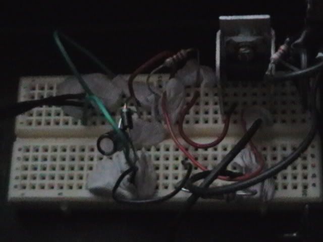
Ok Pics of my circuit coming ;)
They are a bit bad, but tried to do all I could to take best shots.
 
The plain circuit
White blobs are prestik (sticky tack) by the way
Keep the wires in ;)
IMGA0921.jpg


Back
Top