
Welcome to Laser Pointer Forums - discuss green laser pointers, blue laser pointers, and all types of lasers
How to Register on LPF | LPF Donations

Navigation
Install the app
How to install the app on iOS
Follow along with the video below to see how to install our site as a web app on your home screen.
Note: This feature may not be available in some browsers.
More options
You are using an out of date browser. It may not display this or other websites correctly.
You should upgrade or use an alternative browser.
You should upgrade or use an alternative browser.
My 'Daedal Circuit' Confusions
- Thread starter Comidt
- Start date


")
Comidt said:So do you see any problems with it?
If you don't, I will rebuild for like the tenth time.
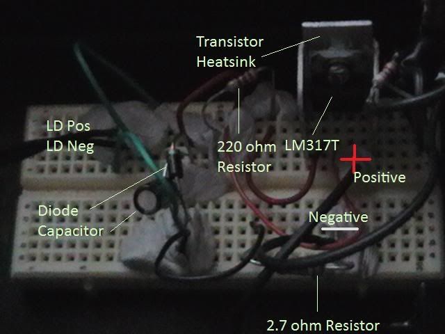
The only thing that could be wrong is that the LD pos is connected to the wrong side of the resistor, would that even make a difference. :-/
Yes and yes. The output current has to flow through the resistor to the LD. You have the LD connected directly to the output pin. The 317 adjusts the current so that 1.25V is dropped across the resistor.
P.S. Those perfboards are much easier to use if you use solid core wire (and you don't have to worry about a loose strand straying to where it should not be).

")
Benm
0
- Joined
- Aug 16, 2007
- Messages
- 7,896
- Points
- 113
Hehe.. get a new breadboard once you've used it often enough to lose contact pressure - they're only a few bucks. Also, one with postive and negative supply rails makes much easier to see what you are doing.
Comidt said:Ok I did that, couldn't see the dot!
So changed to a 3.7 ohm resistor, worked fine, normal brightness.
Then, I turned it on and it was very dim! :-[
I can't get it to work now, has it been killed? :'( :'( :'(
The 3.7 ohm resistor would have placed the output current around 338mA (1.25V/3.7ohms = 0.338). That's a lot. Was the LD heatsinked and how long did you leave it on for? You may have killed it.
Gazoo
0
- Joined
- Jun 9, 2007
- Messages
- 3,206
- Points
- 38
Welcome to the "my diode went poof" club... :'(
At least you know what was wrong with your circuit. Daedal said to put 3 silicon diodes in series with the output to test it before hooking up the diode. Also as Benm pointed out, the contact pressure in the holes of your breadboard might not be good.
Personally I would lose the breadboard and use a PC board with a variable trim pot. Solder joints are much more reliable. I am using a Radio Shack 3 watt 25 ohm rheostat. It is a bit on the big side, but I have no other resistors in the circuit and it works perfectly as long as the voltage is 6 volts or more.
laserrod
0
- Joined
- Aug 3, 2007
- Messages
- 342
- Points
- 0
Comidt man,
That plugboard is a accident waiting to happen.
Power circuits don't work well on the plugboards, holes wareout, loose tension.
You need to make a schematic from your plugboard and then go back to Deadals
schematic. Are we having fun? ;D ;D ;D
Hey, I've been there man, wiring mistakes, intermintant connections ruin days.
Cheer up, if you trace backwards and then do it again,; you will reconcile your wiring problem!
It's a skill. Give it all you got. Live by thy schematic!!!!
If it don't work, wiggle each connection while you watching your current meter through your dummy LASER (load of 3 series diodes(1n400x or somthing)). Learn what a bad connection does to the perfect circuit!
TIP: Run your batt. through a 1 ohm (or close) resistor to the circuit and measure the volts across it, no voltage means no current (ohms/volts=current). I use 1ohms .5watt ohm resistor as cheap a fuse. If you goof up wiring, your just loose a $.02 resistor. heat, smoke, poof!
I've saved my devices from my stupid mistakes. HA HA ;D ;D
That putty sucks, I can't see your misstake, if ones exits.
Find a small small dbl convex lense and a tube of correct lenth to tape or hot glue to you cam. lense for clear close-ups. I made a close-up tube/lense that fits over my zoom tube and it was easy!
Also: I always solder a 22-26 gauge solid wire to too fat or skinny components leads so to not ruin the plugboard, sometimes I double up each connection for redundancy on high current connections. Two plugboard connections better than one.
Your fearless, be disiplined.
Cheers [smiley=beer.gif] [smiley=beer.gif]
Gazoo
0
- Joined
- Jun 9, 2007
- Messages
- 3,206
- Points
- 38
Too much current...you said you were running it with 500ma's, then 400ma's. Even though it did not die right away, chances are good the diode was doomed from too much current. Also bad breadboard connections would not help either.