

- Joined
- Sep 20, 2016
- Messages
- 7
- Points
- 3
Hello! I am an occasional reader of Laser Pointer Forums. I have one more regulator board to contribute that uses the MP3412 (https://www.monolithicpower.com/DesktopModules/DocumentManage/API/Document/GetDocument?id=1389).
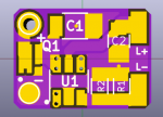
The board was made in KICAD, and I've designated it the MP3412 version 1.0.
The board dimensions are slightly smaller than the Benboost 5.1; OSH Park reports the dimensions to be 11.2 by 8.2 mm.

Front View

Back View
This board has the intent of:
The MP3412 also tolerates an open load, requiring a power-cycle to restart the regulator if the load disconnects. Note that the output is also limited to 5 Volts.
List of Components
In addition, you'll see that there is 1 capacitor on the input, and 1 capacitor on the output. I followed the datasheet recommendations for capacitance, and found satisfactory results. If others are wanting to experiment with this regulator, PLEASE take this design and modify it to your heart's content to get better performance. Some examples:
I'm using the DMP2039UFDE4/DMP2039UFDE as Reverse Voltage protection again. It works well enough and is small.
Like I've said in my Benboost 5.1 posting, other PFETs with similar footprints are available. If one wants to swap PFETs, look for:
Attached Files
The KiCAD files are in a "MP3412_files.7z" archive, but it appears that Laser Pointer Forums does not allow the upload of .7z files. Another member suggested I append the filename with .avi as a workaround. Rename the archive by removing .avi after you download.
I've only attached each board's .kicad_pcb and .sch files. Opening either will create a project in the folder, and this project will be missing libraries tied to the files. Opening the PCB should work on its own without adding libraries.
Opening the schematic will show blank devices until the instructions in "README Schematic.txt" file are followed. Schematic and footprint libraries are included in the attached ".pretty" folders.
If anything is missing or unclear, let me know!
Functionality Confirmation (steady-state regulation)
My application of the MP3412 regulator is to add low input-voltage capability for flashlights. I am currently using the Benboost 5.0 and 5.1 as a constant current LED driver for this, but if I want to power a single LED using a single 1.5 V cell, the MP3412 can be used instead.

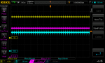
As a reference, this is the regulation of the Benboost 5.0 at a ~50 mA setpoint with an input of 2.4 V. The scope has an offset on V_in due to how I was probing signals; I had to measure on the high side of the resistors that control the regulator setpoint.

This is the steady-state regulation of the MP3412 at a ~50 mA setpoint with an input of 1.2 V (the scope has an offset due the same reasons as on the Benboost). The smoothness demonstrated in this capture was a significant factor in selecting this regulator for my usage.
When building this regulator circuit, ensure to test your output using a test load and an oscilloscope when you can before powering expensive diodes. Look for I_out and V_out.
Because this circuit was built nearly straight from the datasheet, minus a number of components I did not find necessary for my application, I am releasing it without much of an official license. Basically, if you are making revisions or versions based off of this board, please observe the GNU LGPLv3 license.
Feedback would be welcome, but I am not planning to make many modifications in the future. As noted, please modify this regulator circuit to your needs, and submit your own revision to LPF (or make an EAGLE equivalent, that'd probably help some people).
The board was made in KICAD, and I've designated it the MP3412 version 1.0.
The board dimensions are slightly smaller than the Benboost 5.1; OSH Park reports the dimensions to be 11.2 by 8.2 mm.
Front View
Back View
This board has the intent of:
- Providing an open-source boost regulator that can use a wide variety of battery sources (input range is 0.8 to 4.4 V).
- Reducing the output current ripple as compared to other regulators.
The MP3412 also tolerates an open load, requiring a power-cycle to restart the regulator if the load disconnects. Note that the output is also limited to 5 Volts.
List of Components
- C1 [CL31B106MOHNNNE]
- C2 [CL21B225KOFNNNE] or [CC0805KRX5R7BB225]
- L1 [ASPI-0418FS-4R7M-T3] or [NRS4018T4R7MDGJV]
- Q1 [DMP2039UFDE-7]
- R1 and R2 - Setpoint resistors; I_diode = 0.2V/R_Sense
- U1 [MP3412] - Various part numbers exist based on the batch ordered by the distributor. I understand they are the same electrically (no change in operating frequency like the LM3410X vs LM3410Y)
In addition, you'll see that there is 1 capacitor on the input, and 1 capacitor on the output. I followed the datasheet recommendations for capacitance, and found satisfactory results. If others are wanting to experiment with this regulator, PLEASE take this design and modify it to your heart's content to get better performance. Some examples:
- L1 - The parts I used are small and have higher resistance than the inductor used on the Benboost 5.0 or 5.1. This increases power dissipation (decreasing efficiency) and limits the power rating of the inductor. If someone wants to build this regulator for greater performance, the inductor would be a good place to make changes.
- R1 and R2 - This depends on your current setpoint, as I_diode = 0.2V/R_Sense
I'm using the DMP2039UFDE4/DMP2039UFDE as Reverse Voltage protection again. It works well enough and is small.
Like I've said in my Benboost 5.1 posting, other PFETs with similar footprints are available. If one wants to swap PFETs, look for:
- the R_DS(on) at the voltage you plan to power your regulator with
- the footprint of the PFET to match
- the current rating of the PFET
- the Drain-Source Breakdown Voltage rating of the PFET (20V or more should be good)
- the Gate Threshold Voltage rating of the PFET (min voltage to activate the PFET, or give max R_DS(on))
Attached Files
The KiCAD files are in a "MP3412_files.7z" archive, but it appears that Laser Pointer Forums does not allow the upload of .7z files. Another member suggested I append the filename with .avi as a workaround. Rename the archive by removing .avi after you download.
I've only attached each board's .kicad_pcb and .sch files. Opening either will create a project in the folder, and this project will be missing libraries tied to the files. Opening the PCB should work on its own without adding libraries.
Opening the schematic will show blank devices until the instructions in "README Schematic.txt" file are followed. Schematic and footprint libraries are included in the attached ".pretty" folders.
If anything is missing or unclear, let me know!
Functionality Confirmation (steady-state regulation)
My application of the MP3412 regulator is to add low input-voltage capability for flashlights. I am currently using the Benboost 5.0 and 5.1 as a constant current LED driver for this, but if I want to power a single LED using a single 1.5 V cell, the MP3412 can be used instead.
As a reference, this is the regulation of the Benboost 5.0 at a ~50 mA setpoint with an input of 2.4 V. The scope has an offset on V_in due to how I was probing signals; I had to measure on the high side of the resistors that control the regulator setpoint.
This is the steady-state regulation of the MP3412 at a ~50 mA setpoint with an input of 1.2 V (the scope has an offset due the same reasons as on the Benboost). The smoothness demonstrated in this capture was a significant factor in selecting this regulator for my usage.
When building this regulator circuit, ensure to test your output using a test load and an oscilloscope when you can before powering expensive diodes. Look for I_out and V_out.
Because this circuit was built nearly straight from the datasheet, minus a number of components I did not find necessary for my application, I am releasing it without much of an official license. Basically, if you are making revisions or versions based off of this board, please observe the GNU LGPLv3 license.
Feedback would be welcome, but I am not planning to make many modifications in the future. As noted, please modify this regulator circuit to your needs, and submit your own revision to LPF (or make an EAGLE equivalent, that'd probably help some people).
Attachments


Last edited:


 ). My plan was to use the Benboost, and 635 nm diodes from a company that I can name later if desired. After validating the Benboost Mini 5.0, I had determined that the current ripple was too great to safely use for the 635nm diodes; the operating range was between 30 and 40 mA, while the ripple was ~+/-12.5 mA (see above for ~25 mA pk-pk ripple) according to my scope.
")