Welcome to Laser Pointer Forums - discuss green laser pointers, blue laser pointers, and all types of lasers

LPF Donation via Stripe | LPF Donation - Other Methods

Links below open in new window

ArcticMyst Security by Avery

Momentary Switch Diagram

Joined
Aug 6, 2009
Messages
260
Points
0
Howdy, folks! I would appreciate help from the gurus of DIY here.

I have a TopLaser 302 with an iffy clicky. I hope to solder the contacts from the switch to the driver with thin wires until I can get a replacement for the switch.

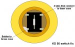
So that I whoa! not fry something, I would like to know the input/ouput poles of such switches. :bowdown:

TIA, and if someone has a switch or two to sell, I would gladly buy em, and appreciate it to boot! :beer:


Joined
Mar 20, 2008
Messages
1,341
Points
0
I think clicky switches don't have input or output, it's just on or off.
 
Joined
Oct 26, 2007
Messages
5,438
Points
83
With so many different switches it'd be hard to tell you the exact specification. What I do, if I have such a switch, is use a multimeter and test the resistance between the terminals of the switch for each switch state.

Unless you take a picture of how your switch was originally soldered and work from that, you might want to just test it with the multimeter as well--just to be sure.
 
Joined
Jul 24, 2007
Messages
2,749
Points
0
As has already been said these switches vary a lot, I did this drawing to show how to get the switch on a KD50 to work better..... It may be the same problem with yours, the outer contacts are folded back and are just pressed into the case and when the brass tarnishes you get intermitant contact.

The connections on this one are the 2 middle pins are soldered together, being a green laser the positive end of the battery touches these.

I just soldered one of the outer pins to the case to get good contact.

Hope that helps.
Regards rog8811
 

Attachments

  • KD50 switch fix01.jpg
    KD50 switch fix01.jpg
    94.6 KB · Views: 852
Joined
Aug 6, 2009
Messages
260
Points
0
TQ to y'all for your responses, am I glad I didnt blindly YOUCH! solder.

Since there are 4 contacts to the momentary switch, I am assuming one comes TO/from? the switch from/to? V-, the other FROM/to? the switch to/from? a limiting resistor; while the other two are anchoring solder points.

I didnt know, just want to make sure before I smoke the board. :bowdown:

(Hehheh :thinking:laughs, nervously:thinking:)

Aww you can tell, it's been a while since I have been in the highs and lows of digital and/or analog electronics. :wtf:
 
Joined
Oct 26, 2007
Messages
5,438
Points
83
Honestly, get a multimeter and test it yourself. The switch might even be symmetric, so you won't know which pair connects anyway without testing. I've been surprised by what connects to where in switches before, and I'm glad I did some testing before I had to solder and unsolder the switch connectors.
 
Joined
Aug 6, 2009
Messages
260
Points
0
I appreciate your advice, B^2.

Guess using the continuity function is another possible test on the multi-meter?

Danka.
 
Joined
Sep 20, 2008
Messages
17,622
Points
113
Yes.... the continuity function of your DMM (if your DMM has one) will let you
know which pin of you switch does what...

Jerry


Top