Welcome to Laser Pointer Forums - discuss green laser pointers, blue laser pointers, and all types of lasers

LPF Donation via Stripe | LPF Donation - Other Methods

Links below open in new window

ArcticMyst Security by Avery

Microboost Solder Job Question

Joined
Sep 17, 2010
Messages
3
Points
0
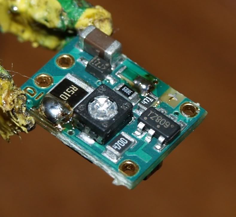
I am working on setting up my microboost driver to drive a 445nm diode close to 1A. I just did the solder bridges the other day and managed to get a little bit more solder than I wanted on one of the bridges. Is this likely going to be a problem? Here is what it looks like:


Boost Driver front by stickyb00t, on Flickr
Notice the big old glob of solder on the lower bridge. Is that going to be okay? It does not appear to be shorting anything else out. Should I attempt to remove some of the solder?


Boost Driver back by stickyb00t, on Flickr
 
Last edited:


Morgan

0
Joined
Feb 5, 2009
Messages
2,174
Points
0
As long as the blob only connects between the negative rail, (the strip of copper at the bottom of the board in the orientation you have it there), and the large format resistor you should have no problems. I can't properly see how good the joint is for integrity but it looks okay. It may mean you have to be careful when installing it that it doesn't short against the host/heatsink or whatever but electrical/insulation tape is often used to mitigate this. If you are concerned, you can gently scrape some solder away or file it, (be sure to remove any swarf or filings to prevent shorts elsewhere), but you should be fine.

I can't quite tell if you have a solder bridge on the underside, (or bottom picture), between the negative output and the small capacitor. If there is then this is also fine and is pointed out in the manual. The capacitor contacts are continous with the output terminals anyway.

When you come to setting it on your testload, you will get a good idea if there are any problems as you will not achieve the expected range.

M
:)
 
Last edited:
Joined
Feb 5, 2008
Messages
6,252
Points
83
You use too much solder, both on bridges and on wires - try to use only as much as necessary to make connection. Also, use external flux - it's magical :D

Here is my very first attempt at making the same solder bridge, and note, I also used too much solder and basically , it is far from great.
P8120125.jpg

On second attempt I made much better solder connection (a laser for x90z75ek) but I didn't bother to photograph it.
 
Last edited:
Joined
Sep 17, 2010
Messages
3
Points
0
I can't quite tell if you have a solder bridge on the underside, (or bottom picture), between the negative output and the small capacitor. If there is then this is also fine and is pointed out in the manual. The capacitor contacts are continous with the output terminals anyway.
:)

It kind of looks this way in the picture, you are right, but as far as I can tell this is just excess flux (causing the shiny look to that spot), and not actually solder.

Thanks for the input!
 

drlava

0
Joined
Mar 7, 2007
Messages
1,152
Points
0
The second one looks good. Just a note, you can bridge to the end of that 471 resistor and not have any trouble. I do this on all of the presets.
 
Joined
Feb 5, 2008
Messages
6,252
Points
83
The second one looks good. Just a note, you can bridge to the end of that 471 resistor and not have any trouble. I do this on all of the presets.
Yeah I can see the trace, it's connected anyway - what about that 3,09 ohm resistor, what if a solder blob catches that?

Just asking :p
 
Joined
Aug 13, 2010
Messages
839
Points
28
An inch of copper desoldering ribbon would clean that up nice and pretty.
*might be a good idea to hold it with something other than your fingers, it heats up pretty quick when you apply heat to the other end* XD
 
Joined
Feb 5, 2008
Messages
6,252
Points
83
An inch of copper desoldering ribbon would clean that up nice and pretty.
*might be a good idea to hold it with something other than your fingers, it heats up pretty quick when you apply heat to the other end* XD
It's called soldering wick, or soldering braid - just to clarify :)

:beer:
 
Joined
Sep 24, 2010
Messages
12
Points
3
I agree, soldering braid really help especially for big globs but sometimes it will suck out too much solder and you loose your bridge. The best thing for bridging on the SMD's is a gel or liquid rosin flux from an applicator and to use solder that contains no additional flux. Apply the flux to the SMD's spots you want to solder, apply solder to your iron tip, one touch to both surfaces and you should have a nice tight bridge. Another thing is the type of soldering iron tip you use, short cone pencil style is what i like to use cause you get a fine tip for SMD but you still have a thick reserve shaft for heat unlike the typical pointed Weller tips that are like an inch long cone and pull all your solder half way up the cone.


Top