Welcome to Laser Pointer Forums - discuss green laser pointers, blue laser pointers, and all types of lasers

LPF Donation via Stripe | LPF Donation - Other Methods

Links below open in new window

ArcticMyst Security by Avery

Math help...Running 2 LD's in series

Joined
Mar 26, 2010
Messages
3,220
Points
0
I'm just curious as to why you don't really want to wire them parallel and use balance resistors?


Joined
Dec 23, 2008
Messages
3,948
Points
63
^^^^ i don't know what i want now. lol. from reading i thought that it is safer to use them in series. so that was my main factor. but if you can tell me more about parallel i'd be open to it.

michael
 
Joined
Mar 26, 2010
Messages
3,220
Points
0
Well running them in parallel IS bad... if you have no kind of current balancing. However if using current balancing resistors, there are really no issues with running them in parallel. For two locs it doesn't matter regardless of how you do it, since you'd still be in the voltage range of the P3 running them in series. However if you tried to run say.. two high power 405's in series, you might run in to problems.. Though i'm not exactly sure what the voltage ceiling is on the P3's without looking it up or asking drlava.
 
Joined
Dec 23, 2008
Messages
3,948
Points
63
i think the p3 takes up to 24vdc. but for the sake of not over heating, i am running 12vdc


edit,, i copied this from lavas website "Power input: 5-24VDC (Output 0-23V)"
michael.
 
Last edited:
Joined
Mar 26, 2010
Messages
3,220
Points
0
The input voltage isn't the issue. It's the maximum it can output at.

Though here's a good example of diodes run in parallel, using balancing resistors.

http://laserpointerforums.com/f65/8-diode-445-build-64296.html

I just dug around PL for some info on the P3 and it looks like it's a linear so you just need to give it more than the series Vf+drop.

I also saw this post which is interesting.. About putting a .1uf cap across each diode you have when running them in series.

Help - Actually Hate the P3 Driver...
 
Joined
Sep 12, 2007
Messages
9,399
Points
113
I'll try to go a little more in depth

attachment.php


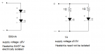
With series circuits, the current must be the same in each component.
With parallel circuits, the voltage must be the same in each component.

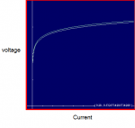
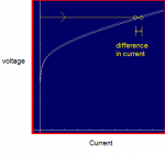
If we look at IV graphs for two hypothetical diodes, they might look very close at first glance:

attachment.php


But remember 
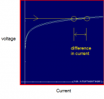
we can only ensure the voltage is the same on each.
That means the current can differ by quite a bit:

attachment.php


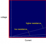
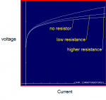
Resistors have a linear IV graph (in accordance with ohm's law):

attachment.php


So we add one to each diode. This makes the curve more steep:

attachment.php


So if we look at the curve of the two hypothetical diodes with resistors:

attachment.php


This might look pretty much the same as what we started with, but since it's more steep:

attachment.php


The difference in current is substantially reduced.
 

Attachments

  • series vs parallel.png
    series vs parallel.png
    13.5 KB · Views: 1,574
  • parallel1.png
    parallel1.png
    5.8 KB · Views: 377
  • parallel2.png
    parallel2.png
    8.3 KB · Views: 342
  • parallel3.png
    parallel3.png
    8.9 KB · Views: 365
  • parallel4.png
    parallel4.png
    10.3 KB · Views: 393
  • parallel5.png
    parallel5.png
    6.6 KB · Views: 386
  • parallel6.png
    parallel6.png
    8.3 KB · Views: 338
Last edited:


Top