

Jufran88
0
- Joined
- Feb 9, 2011
- Messages
- 578
- Points
- 0
LED Maglite 3D Direct Drive SST-90 5700K w/ aspheric lens Build + Info
I have been plotting this build for awhile now and after reading tons of information, waiting for parts to arrive, and school ending; time has allowed me to finally do this build~! I'm no flashaholic so bear with me if mess some things up.
I'll be direct driving this SST-90 with 3 D cell NiMH batteries,but why 3? Well, the forward voltage of these LED reach up to 3.87V at 9A (2.5Vf min and 3.25Vf typical) and a fully charged D cell will give you roughly 1.5V (1.2V nominal). So 3 fully charged cells will give about 4.5V and that is ok becuase:
- LEDs have an operating voltage range
- Batteries under load will sag and probably drop down to 3.7V-3.9V
Here's the parts breakdown:
- LED Maglite 3D (new cree XP-E emitter, same rebel reflector)
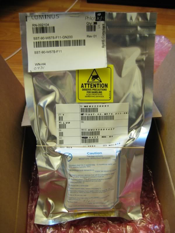
- SST-90-W57S-F11-GN200 @ Avnet (This is the brightest by flux and bin number, but Luminous has revised their codes/bins recently)
- 20 gauge silver plated copper telfon insulated wire
- 3 D size 10,000 mAh Tenergy NiMH batteries
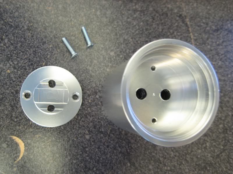
- Der Witchel SST-90 heatsink @ CPF
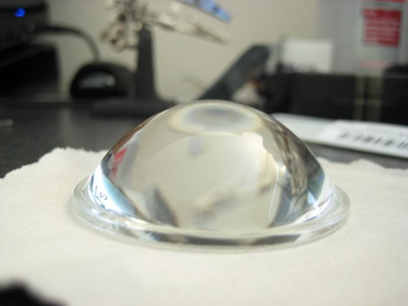
- DX glass aspheric lens (sku: 12834)
Driver options:
Since this is a DD built there are no drivers involved, but for information sake, here are some drivers available for SST-50/90 emitters and probably other emitters as well.
- Dealextreme: SST-90 (sku: 50026) SST-50 (sku :50025)
- DIW driver: Adjustable 10A linear LED driver
- Der Witchel driver: High efficient 5A/9A Buck Converter LED Driver for SST-50, SST-90
- LDO10C driver: Emerson Network Power - LDO10C Series WebSheet (can be converted to buck or boost)
- Sector Cleared: TBA
- TaskLED: LED drivers and PWM control
Heatsink options:
There are a few options to use if you are using a bare emitter or star mounted.
- Britelumens: SST-50/90 Custom heatsinks for C/D Mags (bare emitter)
- Der Witchel: SST-50/90 kits (bare emitter)
- Download: Multi-Sink (for star mounted or bare emitters)
Optic options:
This LED will generate a lot of heat upwards to 35 Watts of heat (3.97*9A = 35.73W) so for prolong duty plastic lenses will start to melt, and if you have a plastic reflector. If you don't plan on using the light for extended periods of time then you could probably get away with the original lens and reflector. Now, the lenses listed below are jus some out of many possible lenses. Any glass lens would do fine.
- Borofloat lenses: borosilicate glass. Able to withstand a great amount of heat. Up to 94% light transmission.
- UCL lenses: AR coated, low iron float glass. Good thermal durability. 99% light transmission.
- Aspheric lenses: Good for "throw" or distance. DX and Melles Griot offer some good ashperic lenses.
Reflector options:
There are possibly many types of reflectors and since this light gives off a lot of heat you might want to use an aluminum reflector so it won't melt under prolonged use.
Cam - This is what the stock Maglite uses, which enables the light to be focused.
Camless - opposite of a cammed relector.
SMO - Smooth; designed for better throw, but may show rings or imperfections on the LED (rings)
OP - Orange Peel; reflect more light, smooths beam inperfections and better for spot. Found in many high quality flashlights
HOP - Heavy orange peel
MOP - Medium orange peel
LOP - Light orange peel
VLOP - Very light orange peel
Hybrid - Combination of both, smooth near the emitter and the rest with orange peel.
Wire options:
Since this light will be direct drive, the wire gauge, type of conductor (copper, silver, etc.) and length is a big factor in how much resistance is added since:
R = pL/A where p (rho) is the electrical resistivity of the conductor, L is the length in meters, and A is the cross section area of the conductor in m^2.
Silver is the best at both thermal conductivity and electrical conductivty, so I went with teflon insulated silver plated copper wire since pure silver wire is pretty expensive.
Now if your going to be using a driver to power an LED it's not as important to invest in expensive wires just as long as they are capable of the desired current going through them.
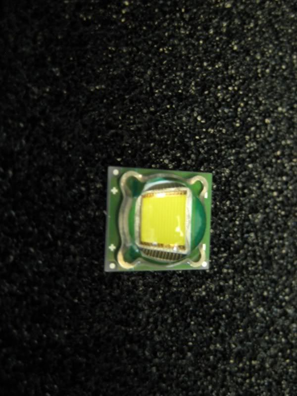
SST-90 options:
The SST-90 can either come as an SMD chip or mounted on a star. I chose the SMD chip to go with the heatsink I picked out. There are heatsinks for the star SST-90s as well if you want to go that route. In my opinion that the chip mounted on the star would be easier to work with because you don't have to worry too much about mounting the small SMD chip on the heatsink. However, the stars cost a bit more than the SMD version.
Also, I wanted to note that Luminous, the maker of these emitters, has recently changed the binning and labeling for reasons I don't really know. Maybe to compensate for the the actual output?
Data sheet: *here*
Binning and labeling: *here*
According to the old datasheet the highest by flux and bin are as follows:
Star: SSR-90 W57S-R11-GN200, bin WN-EH
bare emitter: SST-90 W57S-F11-GN200, bin WN-EH
BUILD:
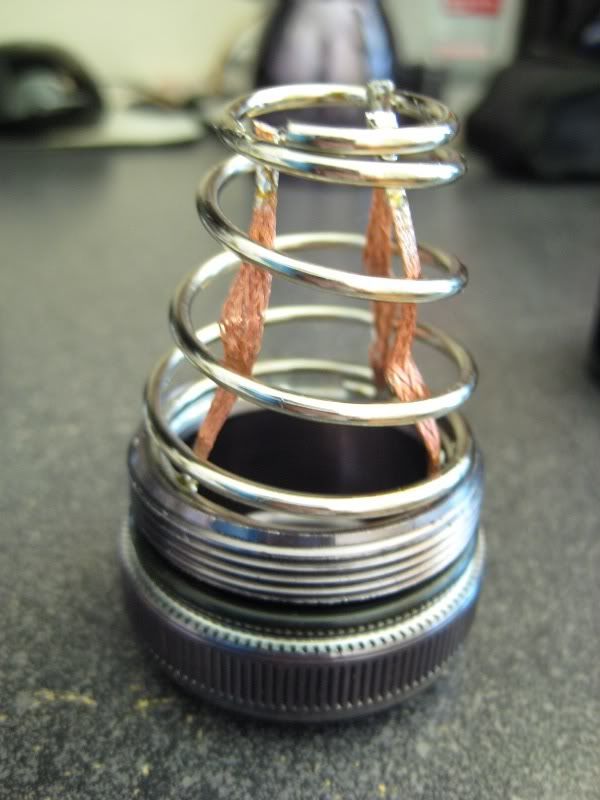
Host prep:
The first step for direct driving is to lower the internal resistance to allow as much current possible without overpowering the emitter. Less internal resistance will output higher current and higher voltage to the LED. So I soldered some copper solder braid to the tail cap spring lower the resistance. The stock spring introduces some resistance (not a lot maybe 30-40 mOhms) due to the length and steel composition.
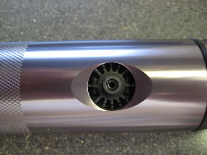
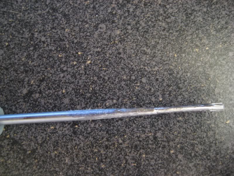
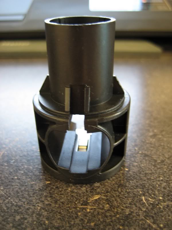
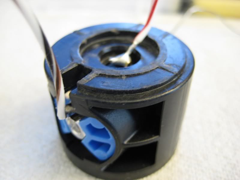
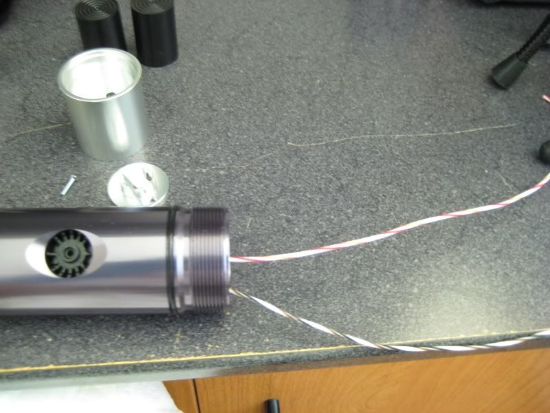
The next step was the stock switch which probably has the most internal resistance in the light (100mOhms or more). To remove the switch from the body first need to take off the rubber cap and under it you will find the clicky with a hole. This is where you will insert a 5/64" or 2mm hex wrench for older models or a Torx T8 for newer LED models. I had the new LED model so I used a torx T8, but I found the shaft too wide to fit the hole so I had to sand it down until it fit all the way. Then just push down until it slides out from the bottom.
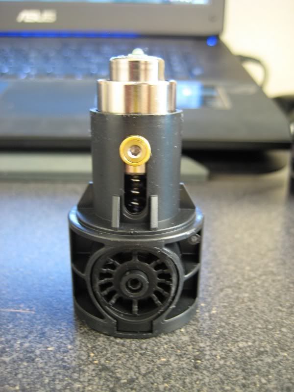
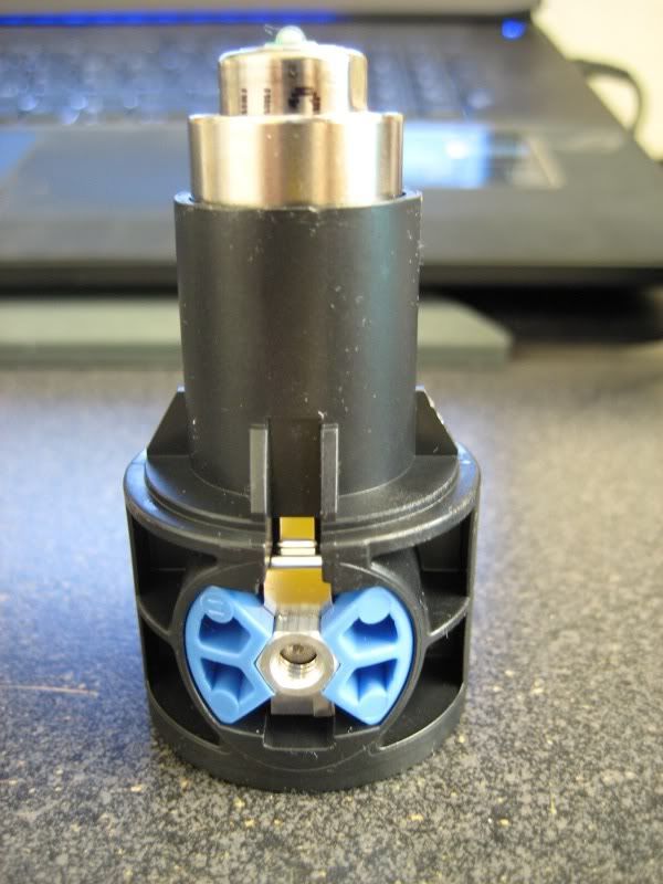
With the bulb assembly out you can take the bulb or LED out using the same tool on the screw holding it in place. I sanded down the bulb assembly to make room for the heatsink. You just simply push the switch out of the bulb assembly and pull it apart.
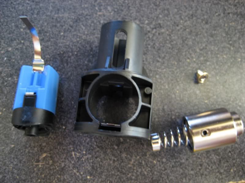
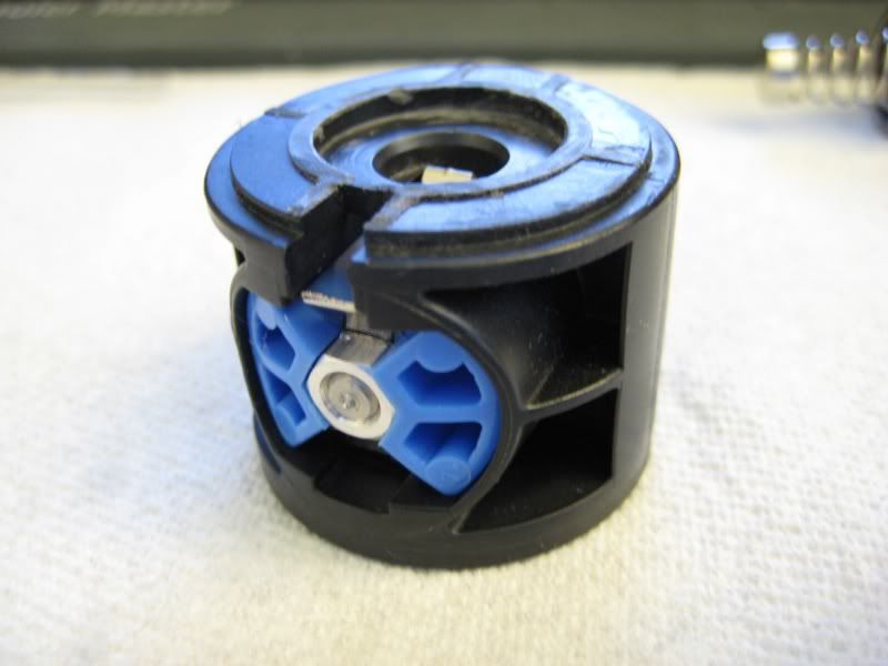
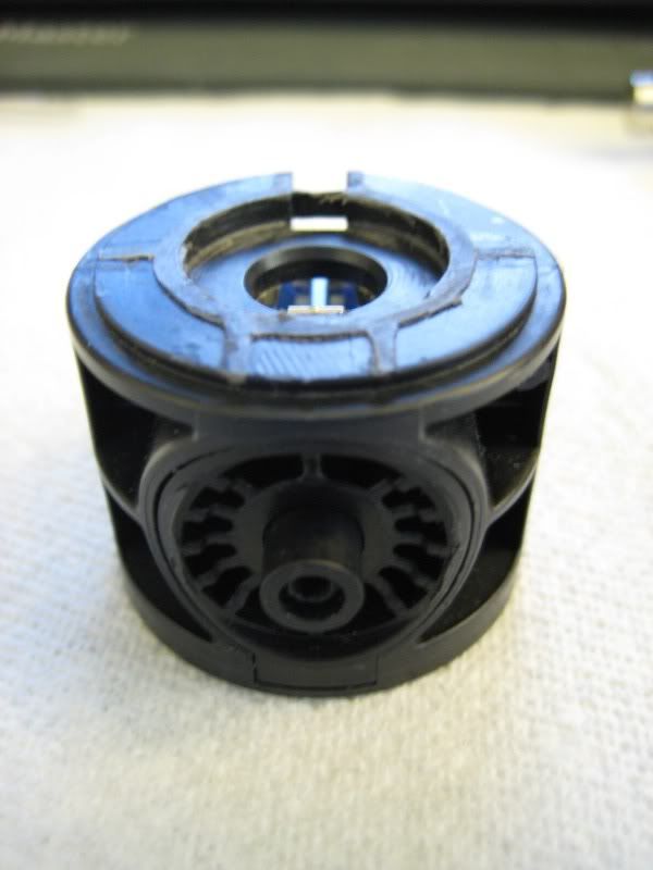
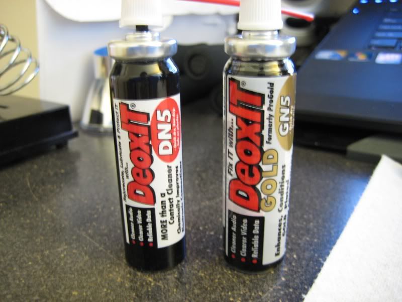
Inside the switch there is a scratched up ring and 2 metal contacts which complete the connection when pressed. I polished the ring and applied DeoxIT to both ring and metal contacts. I didn't actually mod the switch because I was afraid I might actually overdrive the LED. For those unfamiliar with DeoxIT, it is a electronic cleaner, enhancer and protector that cleans oxidized materials, protects it from further oxidation (oxidation will build up resistance over time), and enhances the electrical connection.
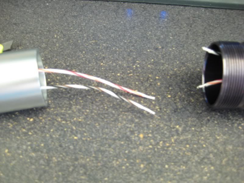
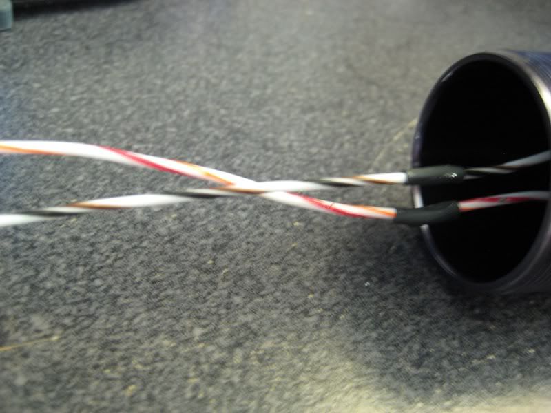
I then soldered some wires to the positive and negative terminals and put it back in the assembly and back into the body of the light.
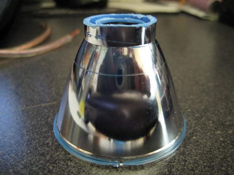
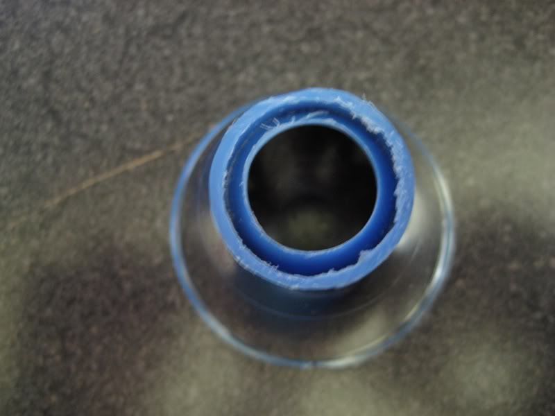
The reflects I had to cut off the cam and widen the the opening to allow the LED through.
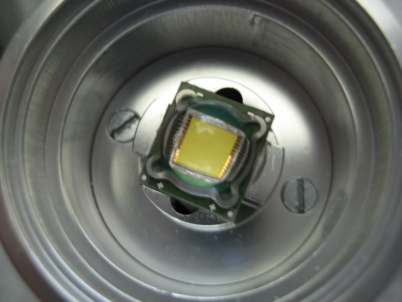
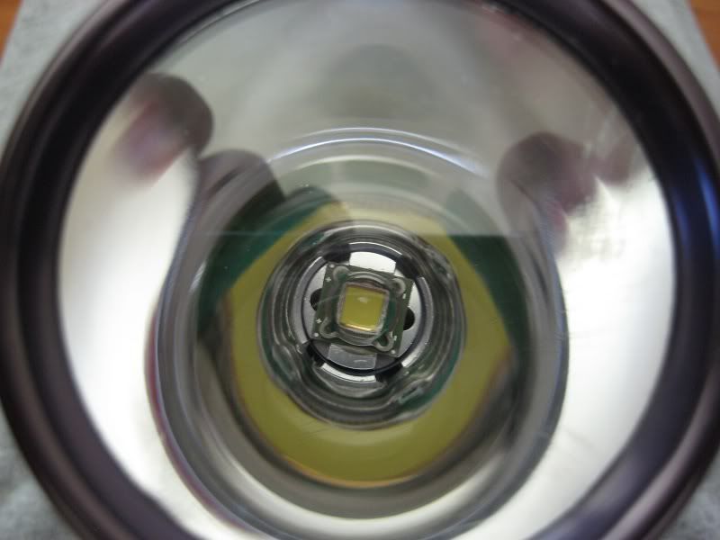
LED prep:
Solder the wires to the LED first and be careful how you handle the emitter because the lens can easily pop off, however if you were to use a star you might have less of that problem. I mixed some arctic silver adhesive to both the emitter and heatsink mount and let it cure overnight. After the adhesive has cured and hardened I soldered the wires together and the light is complete for the most part.
Testing/ Final thoughts:
When I first started this build I ran into a few problems. I got to the point where I just had to test the light to see if it was actually functioning, but as I turned it on for a few seconds the solder somehow melted and the LED dropped to the floor. Horrified and worried that I damaged it, I soldered it back together and as I was about to place it on the heatsink, the lens fell off =[[. I tried to superglue the lens back on the chip, It seems they use some kind of silicone gel adhesive to attach the lens to the chip, and it worked. As I turned it on, no light, nothing. I decided the chip died and had to order another SST-90 and wait for it to get shipped to me.
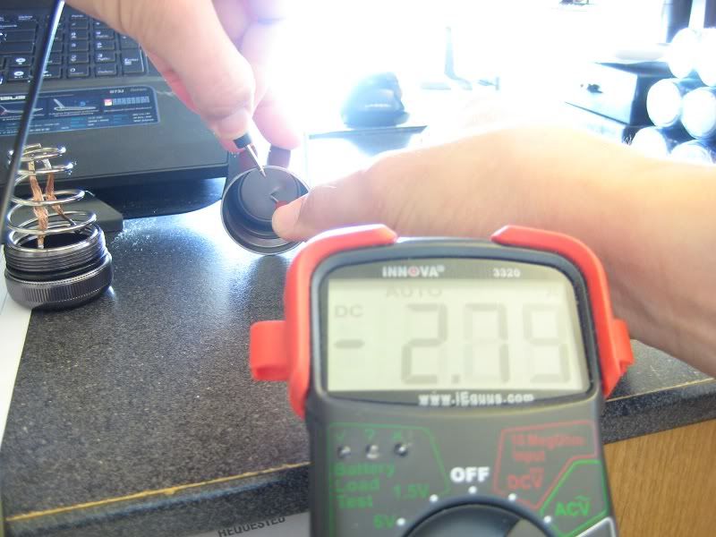
So after 2 tries at this build I finally got it working and was able to run current testing to see how much current was powering the emitter. As you can see using the test leads it measures at 2.79A, which because of the internal resistance of the test leads itself.
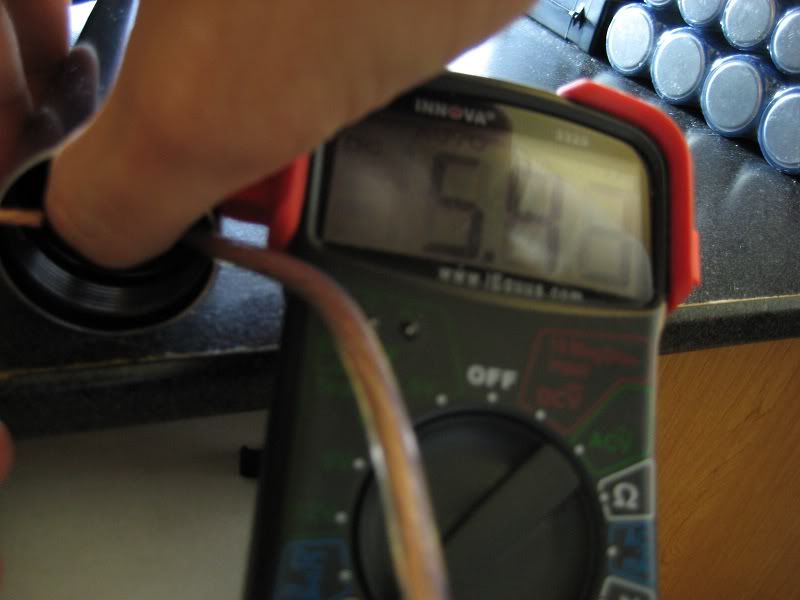
Then I tried using some 12 gauge speaker wire that I use for the home theater set up and I got about 5.43A using that method. There is still some resistance due to the wire so the actual current may be a bit different. Readings could improve if I used a clamp meter, but unfortunately I don't have one.
Sadly, I didn't get to take beamshots because the SST-90 poofed once again. However, when the light was working the beam was incredibly bright. I was amazed and really made me feel accomplished.
I also want to note that as this LED heats up so does the current draw, which is probably why I poofed my SST-90 twice =[ >=[ I am beginning to feel hopeless, but I won't give up. I'll try to attempt this build again in the future using a driver this time. I think I already lost enough money for now, time to save up first.
I have been plotting this build for awhile now and after reading tons of information, waiting for parts to arrive, and school ending; time has allowed me to finally do this build~! I'm no flashaholic so bear with me if mess some things up.
I'll be direct driving this SST-90 with 3 D cell NiMH batteries,but why 3? Well, the forward voltage of these LED reach up to 3.87V at 9A (2.5Vf min and 3.25Vf typical) and a fully charged D cell will give you roughly 1.5V (1.2V nominal). So 3 fully charged cells will give about 4.5V and that is ok becuase:
- LEDs have an operating voltage range
- Batteries under load will sag and probably drop down to 3.7V-3.9V
Here's the parts breakdown:
- LED Maglite 3D (new cree XP-E emitter, same rebel reflector)
- SST-90-W57S-F11-GN200 @ Avnet (This is the brightest by flux and bin number, but Luminous has revised their codes/bins recently)
- 20 gauge silver plated copper telfon insulated wire
- 3 D size 10,000 mAh Tenergy NiMH batteries
- Der Witchel SST-90 heatsink @ CPF
- DX glass aspheric lens (sku: 12834)
Driver options:
Since this is a DD built there are no drivers involved, but for information sake, here are some drivers available for SST-50/90 emitters and probably other emitters as well.
- Dealextreme: SST-90 (sku: 50026) SST-50 (sku :50025)
- DIW driver: Adjustable 10A linear LED driver
- Der Witchel driver: High efficient 5A/9A Buck Converter LED Driver for SST-50, SST-90
- LDO10C driver: Emerson Network Power - LDO10C Series WebSheet (can be converted to buck or boost)
- Sector Cleared: TBA
- TaskLED: LED drivers and PWM control
Heatsink options:
There are a few options to use if you are using a bare emitter or star mounted.
- Britelumens: SST-50/90 Custom heatsinks for C/D Mags (bare emitter)
- Der Witchel: SST-50/90 kits (bare emitter)
- Download: Multi-Sink (for star mounted or bare emitters)
Optic options:
This LED will generate a lot of heat upwards to 35 Watts of heat (3.97*9A = 35.73W) so for prolong duty plastic lenses will start to melt, and if you have a plastic reflector. If you don't plan on using the light for extended periods of time then you could probably get away with the original lens and reflector. Now, the lenses listed below are jus some out of many possible lenses. Any glass lens would do fine.
- Borofloat lenses: borosilicate glass. Able to withstand a great amount of heat. Up to 94% light transmission.
- UCL lenses: AR coated, low iron float glass. Good thermal durability. 99% light transmission.
- Aspheric lenses: Good for "throw" or distance. DX and Melles Griot offer some good ashperic lenses.
Reflector options:
There are possibly many types of reflectors and since this light gives off a lot of heat you might want to use an aluminum reflector so it won't melt under prolonged use.
Cam - This is what the stock Maglite uses, which enables the light to be focused.
Camless - opposite of a cammed relector.
SMO - Smooth; designed for better throw, but may show rings or imperfections on the LED (rings)
OP - Orange Peel; reflect more light, smooths beam inperfections and better for spot. Found in many high quality flashlights
HOP - Heavy orange peel
MOP - Medium orange peel
LOP - Light orange peel
VLOP - Very light orange peel
Hybrid - Combination of both, smooth near the emitter and the rest with orange peel.
Wire options:
Since this light will be direct drive, the wire gauge, type of conductor (copper, silver, etc.) and length is a big factor in how much resistance is added since:
R = pL/A where p (rho) is the electrical resistivity of the conductor, L is the length in meters, and A is the cross section area of the conductor in m^2.
Silver is the best at both thermal conductivity and electrical conductivty, so I went with teflon insulated silver plated copper wire since pure silver wire is pretty expensive.
Now if your going to be using a driver to power an LED it's not as important to invest in expensive wires just as long as they are capable of the desired current going through them.
SST-90 options:
The SST-90 can either come as an SMD chip or mounted on a star. I chose the SMD chip to go with the heatsink I picked out. There are heatsinks for the star SST-90s as well if you want to go that route. In my opinion that the chip mounted on the star would be easier to work with because you don't have to worry too much about mounting the small SMD chip on the heatsink. However, the stars cost a bit more than the SMD version.
Also, I wanted to note that Luminous, the maker of these emitters, has recently changed the binning and labeling for reasons I don't really know. Maybe to compensate for the the actual output?
Data sheet: *here*
Binning and labeling: *here*
According to the old datasheet the highest by flux and bin are as follows:
Star: SSR-90 W57S-R11-GN200, bin WN-EH
bare emitter: SST-90 W57S-F11-GN200, bin WN-EH
BUILD:
Host prep:
The first step for direct driving is to lower the internal resistance to allow as much current possible without overpowering the emitter. Less internal resistance will output higher current and higher voltage to the LED. So I soldered some copper solder braid to the tail cap spring lower the resistance. The stock spring introduces some resistance (not a lot maybe 30-40 mOhms) due to the length and steel composition.
The next step was the stock switch which probably has the most internal resistance in the light (100mOhms or more). To remove the switch from the body first need to take off the rubber cap and under it you will find the clicky with a hole. This is where you will insert a 5/64" or 2mm hex wrench for older models or a Torx T8 for newer LED models. I had the new LED model so I used a torx T8, but I found the shaft too wide to fit the hole so I had to sand it down until it fit all the way. Then just push down until it slides out from the bottom.
With the bulb assembly out you can take the bulb or LED out using the same tool on the screw holding it in place. I sanded down the bulb assembly to make room for the heatsink. You just simply push the switch out of the bulb assembly and pull it apart.
Inside the switch there is a scratched up ring and 2 metal contacts which complete the connection when pressed. I polished the ring and applied DeoxIT to both ring and metal contacts. I didn't actually mod the switch because I was afraid I might actually overdrive the LED. For those unfamiliar with DeoxIT, it is a electronic cleaner, enhancer and protector that cleans oxidized materials, protects it from further oxidation (oxidation will build up resistance over time), and enhances the electrical connection.
I then soldered some wires to the positive and negative terminals and put it back in the assembly and back into the body of the light.
The reflects I had to cut off the cam and widen the the opening to allow the LED through.
LED prep:
Solder the wires to the LED first and be careful how you handle the emitter because the lens can easily pop off, however if you were to use a star you might have less of that problem. I mixed some arctic silver adhesive to both the emitter and heatsink mount and let it cure overnight. After the adhesive has cured and hardened I soldered the wires together and the light is complete for the most part.
Testing/ Final thoughts:
When I first started this build I ran into a few problems. I got to the point where I just had to test the light to see if it was actually functioning, but as I turned it on for a few seconds the solder somehow melted and the LED dropped to the floor. Horrified and worried that I damaged it, I soldered it back together and as I was about to place it on the heatsink, the lens fell off =[[. I tried to superglue the lens back on the chip, It seems they use some kind of silicone gel adhesive to attach the lens to the chip, and it worked. As I turned it on, no light, nothing. I decided the chip died and had to order another SST-90 and wait for it to get shipped to me.
So after 2 tries at this build I finally got it working and was able to run current testing to see how much current was powering the emitter. As you can see using the test leads it measures at 2.79A, which because of the internal resistance of the test leads itself.
Then I tried using some 12 gauge speaker wire that I use for the home theater set up and I got about 5.43A using that method. There is still some resistance due to the wire so the actual current may be a bit different. Readings could improve if I used a clamp meter, but unfortunately I don't have one.
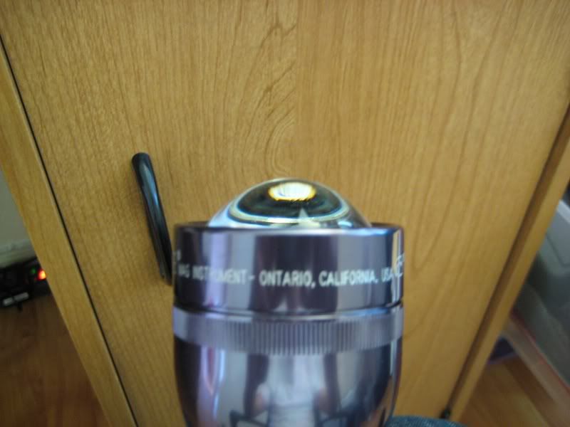
Sadly, I didn't get to take beamshots because the SST-90 poofed once again. However, when the light was working the beam was incredibly bright. I was amazed and really made me feel accomplished.
I also want to note that as this LED heats up so does the current draw, which is probably why I poofed my SST-90 twice =[ >=[ I am beginning to feel hopeless, but I won't give up. I'll try to attempt this build again in the future using a driver this time. I think I already lost enough money for now, time to save up first.
Last edited:


