Hi guys
so i was in the process of my first build and then i ran into a problem. my laser wouldn't turn on!.
Here's the stuff i have:
9mm laser from dtr with a G2 lens in a module
1.8A lazeerer X-drive V6 driver
2x panasonic 18650's 3.7V each
and a switch.
so here is how everything is connected.
1st the two batteries are put in series.
2nd the positive terminal from the batteries travels to my switch
3rd the negative terminal/Gnd travels to the X-drive V- terminal.
4th the negative terminal/Gnd from the laser diode travels to the LD- terminal
5th the other end of the switch travels to the X-drive V+ terminal
6th finally the postive terminal of the laser diode travels to the LD+ terminal
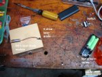
I think everything is correctly attached. Attached is also a picture of the setup(sorry for the mess).
so i did some experimentation with a multi meter. first i measured the voltage at the input of the driver after the switch and i was measuring 7.3-7.4V due to the series combination of the lithium ion batteries in series. so this was correct both my batteries and switch were working.
Then i measured the voltage at the output of the driver( connected to the laser) but i was measuring 0 volts. Then i removed the laser and measured the output voltage and it was still 0 volts. Then i added a 40 ohms resistor and still 0 volts. I dont think my driver that i just bought should be giving me 0 volts at the output when i feed in 7.4V volts.
so i was wondering if you guys think this is a driver issue or the laser is dead. I am thinking of using a simple LM317 circuit (like the one here: https://www.youtube.com/watch?v=2Rjlf7gnXms ) and connect it to the diode to see if it is operational since i have never turned it on before.
looking forward to your reply
Zak
Attachments
Last edited:


