Welcome to Laser Pointer Forums - discuss green laser pointers, blue laser pointers, and all types of lasers

LPF Donation via Stripe | LPF Donation - Other Methods

Links below open in new window

ArcticMyst Security by Avery

Laser Gatling - getting 8 CORRECTED parallel beams from NUBM08 block

Joined
Feb 12, 2016
Messages
589
Points
63
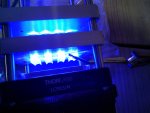
Hi, I am returning with another build about what one can do with a virgin NUBM08 block.
Let us call it - Gatling laser???

You can consider this thread as a continuation of that one:
https://laserpointerforums.com/threads/test-of-diodes-in-nubm08-block-all-at-once.103392/

but now I want to play with corrected beams and not such as they come out from G-ball lenses.

Red Cowboy, you were always right - it is more professional (or LPF-traditional) to do perfect beams from loose LDs in DTR modules but I wanted to try something from a whole bock now when they are finally cheap and do not cost >1000usd as 2 years ago.

From previous work in this subject I am sure everyone knows the classics - Styropyro 40W shotgun video and this recent video (but the description in this last one does not look true to me):

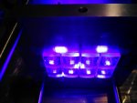
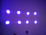
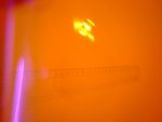
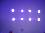
Styropyro's beams look very straight - maybe he managed to get a block with well collimated parallel beams? Mine cheap block from taobao was all opposite but let us see if the correcting lenses would help here...

So the differences from his version will be:
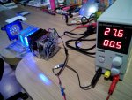
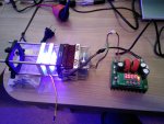
- I use one driver for all 8 LDs connected in series like original PCB circuit allows
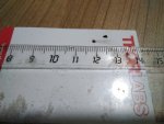
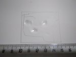
- I use 8 pairs of C-lenses from LSP which have the right passing size to correct beams
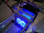
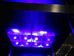
- I mount all on a 60mm cage frame from Thorlabs
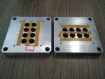
- I use specially CNC-made plates for optics and purpously drilled heatsink for the block

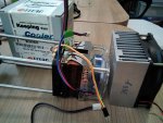
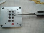
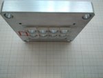
Tried aluminium HS from ali (metal mass was 300g) and copper HS for AMD K8 from the local computer shop. The HS capabilities are very similar - after 5min at 3A curent the temperature sensor shows 46ºC on the surface of the block. But the copper one is more compact.

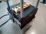
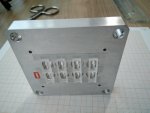
A blank plate from Thorlabs was cut to insert the block and screwed to the HS as well as the block itself. All with Arctic silver paste in between etc. The bars which fit into it hold 2 other Al plates with 8.5mm holes drilled for the beams. Over the plates I attached C-lenses just with double side adhesive tape, so the lens separation be 32mm. Oh, this was not easy - the lenses are sooooo small!!!
The plates can slide on bars in order to find the right position but all lenses move at once due to the design!

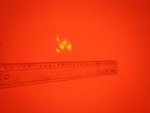
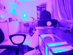
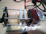
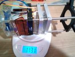
At the edge of the bars I put the lens holder to make all beams focus into one spot as classic teaches. Now the build is ready and weights 1131g - not very light.

Styropyro - if you read this - where did you get the lens to focus?
I do not find any AR coated lenses of 2-3 inch diameter and f>1000mm neither at Thor nor on ebay...
 

Attachments

  • 01.jpg
    01.jpg
    668.4 KB · Views: 34
  • 02.jpg
    02.jpg
    487.1 KB · Views: 33
  • 03.jpg
    03.jpg
    787.8 KB · Views: 34
  • 04.jpg
    04.jpg
    807.9 KB · Views: 33
  • 05.jpg
    05.jpg
    642.5 KB · Views: 35
  • 06.jpg
    06.jpg
    563.7 KB · Views: 34
  • 07.jpg
    07.jpg
    607 KB · Views: 36
  • 08.jpg
    08.jpg
    624.3 KB · Views: 39


Joined
Sep 20, 2013
Messages
17,426
Points
113
You have taken on a great deal of optical correction with this one. I hope that you will not have any problems with the Cyl lens correction as you have them all at the same distances. It could work.......then again, it may not. I might have tried knife edging them to get a tighter beam pattern, but since you have gone this route, I hope you can find a lens that will converge all your beams at the same distance. Good luck to you.
 
Joined
May 12, 2017
Messages
961
Points
93
This is a great project, but it also has certain risks, anyway good luck with your work .
Redcowboy,I think he won't use g2, the removal of the g-ball will shorten the life of the diode ,
If a project uses g2-I will use nubm44-71 blocks, my country is importing a large amount to replace the casio projector Xj-v1, and now the price is 300usd
Paul,yes i agree with you,it is very difficult
 

Benm

0
Joined
Aug 16, 2007
Messages
7,896
Points
113
I guess the success of this project mostly hinges on the diodes in a block being identical, as well as their factory fitted lenses and such, so in the end it could all be focused down onto a single spot.

I hope this works out, and think the chances would be reasonable given the original application of the laser diode block - if they all had very different divergences or would not be aligned well it probably would not work for a projector that well either.
 
Joined
Jul 10, 2015
Messages
9,903
Points
113
The GBall divergence ranges from not good to horrible, sometimes I see nubm06 diodes with pretty good GBall factory divergence but it still needs a beam expander to do work at any distance at all, also the factory alignment in the block may be good but it wont be great, each c-lens pair really needs hand tuning and if using the GBall lenses ..............well I would love to see it work, but I'm sorry to say I doubt it will yield any kind of collimated beam, more of a spotlight although you could burn with it up close although the power will likely be spread out.

Good luck and I would love to see some surprising good results, but please do share your findings regardless, we all learn more when we share. :)
 
Joined
Feb 12, 2016
Messages
589
Points
63
Yes, RC and Trinh, you remember it right - later I was planning to repeat this with a NUBM44 block from v1... and all G-2 lenses over diodes. That's why I made plates with 8.5mm holes - to be useful for cutting M9x0.5 threads in those later...
That should result in all perfectly collimated beams easy to correct in the same way with such a setup...

But first (just to prove concept) I try with the "bad guy in the block" - this cheap NUBM08 block (since it was laying here) where LDs are differently collimated with G-Balls and not perfectly parallel - just to see how good... or bad... it will give the result.

I was even too lazy to adjust C-lenses positions to the centers of the beams - they are installed as if all beams were perfectly parallel. Let's see how good the spot of this "engraver" will be at distance.

If we could install 8 "mini Beam expanders" for each beam then they could compensate for the differences in collimation from each of G-balls but I have no idea how to do this here.
Again, perfectness can be done with G-2 over each NUBM44 but later. This thread is about not-perfect but simple (more or less) system!

Regarding the focusing: the only lens I have for this Thor holder has f=200mm. Looks too short to me. The longest focal distance of 50mm diameter they sell (BB AR coated) is 1000mm.
It seems that Styropyro had one with 3-5 m focal distance. Where could I get such a lens now? Preferably AR coated!
 
Joined
Jul 10, 2015
Messages
9,903
Points
113
@Light superglue: Finding large AR coated lenses has been an issue for me as well, well................ on the cheap that is, I have buckets of scavenged lenses but the coating is none or potluck. I thought styro was using a common household magnifying glass on his block of 05's

I didn't think the expanded beam from those GBalls post concave cylindrical would even fit on the convex cylindrical lens, not far enough apart to yield any kind of beam.
I tested a 44 with a G7 and 6X pair before, it would not play, I expect the GBall would be just about as bad.
Were you able to get anything at all out of them with the 08 GBall that looks a little shorter ?
 
Last edited:
Joined
Feb 12, 2016
Messages
589
Points
63
Well, now the bright part!

No RC, all beams passed well into Plano-convex cylindricals (they are 5-6mm wide after expansion if we do not count the side wings but these do not contain much power), the optimal lens separation where the spot on the wall (5m away) is in total smallest was 31-32mm.

Sure I did not get perfect 2 rows of 4 tight spots on the wall and we see that beams are not very parallel from cheap block and not same tight but I was surprised to see that the spots area did not exceed much the size of the block itself (60x20mm).

So first at 0.5A current I could concentrate beams at 200mm with my lens to a 1-2mm tiny spot and it burns white paper. After the focus point beams diverged into 8 big beautiful almost perfect squares without much artefacts... except some squares have a little of rombs...

Then at 3A current (focusing lens removed) I melted 1 minute through 3mm thick white polystyrene sheet hanging on the wall and this displayed 3 areas of maximum power concentration but the whole light spot (not straight pencil line) passes into a 50x40mm rectangle.
So, like Gatling gun hits are not all into one spot, ha-ha.

You also see that most individual spots are diagonal - could it be because C-lenses rotational positions are not perfect on my adhesive tape???
 

Attachments

  • 09a.jpg
    09a.jpg
    842.6 KB · Views: 27
  • 10a.jpg
    10a.jpg
    506.1 KB · Views: 28
  • 11a.jpg
    11a.jpg
    761.8 KB · Views: 28
  • 12a.jpg
    12a.jpg
    884.2 KB · Views: 29
  • 13a.jpg
    13a.jpg
    692.2 KB · Views: 31
  • 14a.jpg
    14a.jpg
    678.6 KB · Views: 31
  • 15a.jpg
    15a.jpg
    849.2 KB · Views: 29
  • 16a.jpg
    16a.jpg
    662.6 KB · Views: 33
  • 17a.jpg
    17a.jpg
    666.6 KB · Views: 32
  • 18a.jpg
    18a.jpg
    533.4 KB · Views: 30
Last edited:
Joined
Jul 10, 2015
Messages
9,903
Points
113
Yes, in image 17a you can see the spots are skewed from c-lens misalignment.
 

Benm

0
Joined
Aug 16, 2007
Messages
7,896
Points
113
I'm not really sure what's going on here. Looking at picture 14A it seems like the diodes are not all inserted in the same orientation in the block. The mis-alignment doesn't seem to be that large, and may even be due to the photo angle/perspective, but could also be really there.

If that were the case applying the same corrective optics for fast/slow axis would not work well either.
 
Joined
Feb 12, 2016
Messages
589
Points
63
O, almost one week without replies in this thread! It seems to me that after Alaskan had left the forum not many people interested in experimenting with high power are staying here...

Benm, adhesive tape is pretty good for keeping cylindricals in place but shifting them with tweezers is extremely easy - by shifting concave lenses I can shift the direction of the beams and get rid of misalignment (or do it even bigger).

But as next step I am planning to do a knife edging of each of 4 beams row to obtain 2 concentrated beams - this would be a solution for directional issues. Even rombs can be KEdged with decent degree of precision, not only squares. Sure I will have to fix all C-lenses on glue to avoid rotational artefacts prior to this and a lot of work is still to be done with adding 8 mirror mounts etc.
So this thread is supposed to have a long life, I hope.

If there is bad orientation of LDs in the block it does not look much visible and no idea how to correct it - also after KE it should become less an issue...
 

Attachments

  • 19a.jpg
    19a.jpg
    594.4 KB · Views: 12
  • 20a.jpg
    20a.jpg
    463.7 KB · Views: 14
  • 21a.jpg
    21a.jpg
    677 KB · Views: 14
Joined
Jul 10, 2015
Messages
9,903
Points
113
The hand held video you posted has all the beams running parallel to each other, that is they are all aligned well and converged over a short distance, also I wonder if he is using a meniscus lens ?
 
Joined
Feb 12, 2016
Messages
589
Points
63
He shows several caps, some of them must have a converging lens for sure. Even my block beams become square at 15-20cm, so they could be converged into a decent spot without correction. But any firther is mess as you know.

Strange I did not find anyone to sell this type of multibeam portable. Must be because of high price and short duty cicle.

BTW this is my 333rd message here!


Top