Welcome to Laser Pointer Forums - discuss green laser pointers, blue laser pointers, and all types of lasers

Buy Site Supporter Role (remove some ads) | LPF Donations

Links below open in new window

FrozenGate by Avery

Lambda Ruby Laser Head

Another small step forward. Making a sturdy Aluminium rail for the Laser assembly and the Optics. I have mounted the Laser Pump Chamber and the Adjustable Mirror Mounts. The alignment of the Rod to Mirrors should be very close. Then the mirrors can be adjusted later using a small pointer. I will start off using 20mm mirrors for the HR and OC. I have a Pyrex 99.7% for the HR mirror with an AR coating for 633-694nm and I will use a 1064nm as the OC. At 694 the 1064 Mirror should have the correct reflection. I can check it with a 650 pointer and see if I get around 30-50% Reflection.


Some pics
 

Attachments

  • IMG_20171121_233356.jpg
    IMG_20171121_233356.jpg
    40.4 KB · Views: 45
  • IMG_20171121_233436.jpg
    IMG_20171121_233436.jpg
    37.2 KB · Views: 47


I missed this thread the first time while I was in the hospital. Glad I got a second chance to subscribe. These are high on my wish list. Would love to do some portrait holography.
 
I missed this thread the first time while I was in the hospital. Glad I got a second chance to subscribe. These are high on my wish list. Would love to do some portrait holography.


Hope you are well now.


I have a number of items to do yet. I have the parts for the water cooling. I might make some brackets and assemble that soon. Just a standard PC water cooling loop. I am still waiting on the E Core transformer to make the charging circuit for the Capacitor bank. I have a high quality MDS car Ignition coil I will use for the ignitor. Just give it a fast charge pulse with a Mosfet and use the Flyback voltage to ignite it. I think I need to connect the coil reverse polarity to get a Positive pulse from what I have read about igniton coils. I will just couple it to the Flash lamp anode with some 20kv 1a Diodes I have. I have an old E core from a Welder I can use to make the inductor for the flash lamp.

Hopefully I will be able to get some nice Red pulses from it in the next few months.
 
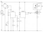
I have been having some fun making the Ignitor board. It's been a while since I have done some Microchip PIC Programming. I used to do a lot of it. I decided to use a 12F675 as it was less components than just One shots and Logic gates. I have also added some safety features in the code. It checks the Fire button is Open for more than 1 second before the Fire is enabled. Then the Fire Button needs to be held closed for more than 1 second before it fires.

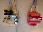
I used an MSD SS Coil for the output. A Top end car igniton coil.

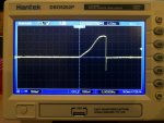
I am happy with the Graphs from the oscilloscope I recorded. The Output looks very nice. I adjusted the Charging pulse to 8 mS after finding out when the coil reached it's peak current. It peaks at 15 Amps just below 8 mS.

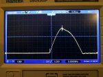
I have not put the HV Probe on the output to confirm but the Input curve should be very close to the output. The Input curve peaks at 450 Volts in about 8 uS. The Coil has a 1:70 turns ratio which will give me about 30 kV on the output. Plenty to trigger a large flash tube using direct Anode connection thru a HV Diode. I do get a nice Arc when I fire it. Easily jumps 1 inch.

Here are some Graphs of the Circuit in action. The first is the voltage across the 0.1 Ohm resistor. It peaks about 1.5 Volts which is about 15 Amps. The second graph is the Flyback voltage on the Coil. It peaks about 450 Volts. The Third is the Schematic. Then an Image of the assembled board.

I havn't included the PIC code but it's freely available if anyone wants to look at it.
 

Attachments

  • IMG_20171208_221405.jpg
    IMG_20171208_221405.jpg
    176.3 KB · Views: 25
  • IMG_20171208_221643.jpg
    IMG_20171208_221643.jpg
    174.5 KB · Views: 26
  • IGNITOR.jpg
    IGNITOR.jpg
    57.5 KB · Views: 48
  • IMG_20171208_221933.jpg
    IMG_20171208_221933.jpg
    152.3 KB · Views: 39
Last edited:
Very nice work, we have a high level builder here folks, I'm going to be following this project :)
 
Hmmm. Everything can be made much simpler. I used a 2 kV trnsformer, a capacitor and a sparkgap which discharged the capacitor in the transformer's primary. The capacitor can be charged through a resistor, so the sparkgap will shoot after a few seconds after pushing the firing button. I don't see any justified reason to use a microchip\microcontroller in a such simple device.
 
Last edited:
Hmmm. Everything can be made much simpler. I used a 2 kV trnsformer, a capacitor and a sparkgap which discharged the capacitor in the transformer's primary. The capacitor can be charged through a resistor, so the sparkgap will shoot after a few seconds after pushing the firing button. I don't see any justified reason to use a microchip\microcontroller in a such simple device.


Of course you are correct. But it's not as much fun.

My aim is to make the whole laser run from a 12 Volt supply. That does limit the design somewhat.
 
Last edited:
I am more curious how your HR and OC mirrors are going to work in this setup. These are usually the greatest expense in building a ruby laser. I guess it will all come down to whether or not it lases when everything else is finished and time to test.
 
I am more curious how your HR and OC mirrors are going to work in this setup. These are usually the greatest expense in building a ruby laser. I guess it will all come down to whether or not it lases when everything else is finished and time to test.


That will be the biggest problem. It might take some time to find a HR and OC that will work correctly. I do have a 20mm HR with a 694nm coating but weather it can withstand the power I will have to wait and see.

The OC I will be trying 1064nm Mirrors. They will pass about 50% at 694mn with the correct one. I did read they can be used for Ruby.
 
I'll be watching with great interest. This is something I've been wanting to try for many years. If you get it figured out and have a supply that doesn't cost an arm and a leg, that will further pique my interest.
 
I'll be watching with great interest. This is something I've been wanting to try for many years. If you get it figured out and have a supply that doesn't cost an arm and a leg, that will further pique my interest.


It will be a nice surprise if I can get it to lase. The only real issue will be mirrors.

Probably the single most expensive component is the Capacitor Bank. Not just any caps will do. Next was the Ruby Head itself.

The rest wont be much cost at all. I will be making an Inverter to charge the caps from a 12 Volt suypply. I already have a design but am still waiting on the E-Core transformer. The Slow boat from China seems to have taken a wrong turn....
 
yeah you can use Ti:sapph mirrors too. since they're tunable about 675-1100nm, my last one used a ti:sapph oc and a ruby HR iirc. I've also used a silvered mirror. both planar makes it hard to align though, but is typical for a high power laser like this.
 
Last edited:
Yeah, I've had parts on that same slow boat from China myself. It gets pretty frustrating when a single item is holding up your whole project. I'll be waiting anxiously to see how this works out.
 
yeah you can use Ti:sapph mirrors too. since they're tunable about 675-1100nm, my last one used a ti:sapph oc and a ruby HR iirc. I've also used a silvered mirror. both planar makes it hard to align though, but is typical for a high power laser like this.


Yep, I have purchased some Ti Saphire Mirrors from Ebay. I dont think they are high power though.


Back
Top