Welcome to Laser Pointer Forums - discuss green laser pointers, blue laser pointers, and all types of lasers

LPF Donation via Stripe | LPF Donation - Other Methods

Links below open in new window

ArcticMyst Security by Avery

Is this correct

Mrmask

0
Joined
Feb 11, 2010
Messages
21
Points
0
Ok I spent yesterday building the power supply for my diode.
I am using the lm317 chip installed in a chip housing.
It can be found here
DC Regulators LM317 LT117 MC34063 Step Up Down *USA - eBay (item 150405545131 end time Mar-15-10 19:24:27 PDT)

I am using a 9 volt 500 milliamp power supply.
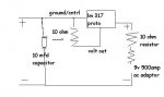
I had some trouble with voltage so I hooked up two resistors one after another before sending it in to the lm 317 chip. After I did this it brought the volts down to 4.9 by measuring the + and - from where it hooks up into the test load. I set the milliamps to 180 between a 1 ohm resistor in a 6 diode dummy load.

So now all I should need is the capacitor between the pos and neg terminals and then my laser diode should lase? I am using a high powered blueray 405nm GGW-H20L.

I built the diagram included. It is my first so don't laugh. I have never done anything like this before but I think I am getting it.

Will this blow my diode?
 

Attachments

  • diagram.JPG
    diagram.JPG
    15.4 KB · Views: 148


Mrmask

0
Joined
Feb 11, 2010
Messages
21
Points
0
Oh and I thought I would mention that the voltage coming out is a bit sloppy but I haven't hooked up a capacitor yet (gonna pick one up tomorrow.) Is there anything to watch out for and will that fix the voltage changes?

Also the ac adaptor was putting out much much more volts from the leads than the rating. I had about 800 milliamps measured before the resistors were put in when I measured the dummy load (it got sizzly hot!)


Should I still ground the Lm 317? I am using the ground/control out to adjust the current. Wouldn't attaching this to my laser display housing create a short circut or something?
 
Last edited:
D

Deleted member 8382

Guest
Wait wait. Did you buy one of these circuits on Ebay and use it where you wrote "lm317 proto"?

Those things are drivers based on the lm317 chip, which is what you want to build, I mean, what you bough is already the driver, it even has the capacitor!
 

Mrmask

0
Joined
Feb 11, 2010
Messages
21
Points
0
I bought it from the same suppliers website (which was down for maintenance.)

I figured it had capacitors but none are linked between the + and - leads as the lm317 uses only the positive side. I am not sure if that makes a big difference.

Yeah I put the chip in the diagram as is. I am not sure of the ratings but I think it has a 100ohm pot (very small changes in milliamps from what I noticed.) 2 capacitors and the lm317 chip. I didn't use the clampy ends as they just seemed too unreliable but there were three solder dots on the bottom marked Vin, ground, and Vout. There are a few resistors on it too and what looks to be a diode. I sent the link as I am not sure how all the parts on the chip work together. Should I get another lm317 and wire it as a voltage chip to go with this one setup for current.

The reading read the same on a test load and a dead similar high powered blueray diode.
 

Mrmask

0
Joined
Feb 11, 2010
Messages
21
Points
0
Oh and should I include the test load into my final product?

I just took a few readings when hooked directly onto the dead diode and it read about 11 volts. With the dummy load connected it read 4.8 again.
 
Joined
Aug 28, 2009
Messages
1,071
Points
0
Oh and should I include the test load into my final product?

I just took a few readings when hooked directly onto the dead diode and it read about 11 volts. With the dummy load connected it read 4.8 again.
The test load is only for setting up the current of the driver. Do not leave it in place with the LD
Your dead diode is open. If it was LED'ed, you could get a close Vf reading.
 
D

Deleted member 8382

Guest
what you need is the lm317 alone, not a driver that uses it!
 

Mrmask

0
Joined
Feb 11, 2010
Messages
21
Points
0
I took off the test load

It still reads 180 milliamps but it reads 11 volts without the load.

I am measuring from the - to the + with the positive tip of my multimeter after the last resistor and the negative on the end of the negative wire on my Ac adapter.
 

Mrmask

0
Joined
Feb 11, 2010
Messages
21
Points
0
The test load is only for setting up the current of the driver. Do not leave it in place with the LD
Your dead diode is open. If it was LED'ed, you could get a close Vf reading.


Does this mean when I hook up my working diode it will send the correct voltage? and cycle back the remaining volts? By open do you mean that it isn't drawing any power and just cycling it through?

my milliamps are 180 and it reads 4.9 volts with the test load. Milliamps stay at 180 but voltage climbs up to 11 without it.
 
D

Deleted member 8382

Guest
Hook the diode where? To the battery? Well, then be prepared to enjoy your new LED soon xD
 

Mrmask

0
Joined
Feb 11, 2010
Messages
21
Points
0
What, no close ups of your design?? please take close up photos of your work.


I need to get some electrical tape before I will be happy. I loosely put some duct tape over the bare wire spots just to test it out.

Worked for 10 minutes straight with no trouble. Worked for short durations 3 times. I am not running this close to max current as I want to put it in a unit that may stay on for close to 6 hours. I have heard of this type of beam passing 200 ma, but I feel like most of the people here are into building pointers more than long running display systems.

I put the module in a lab style heat sink for easier mounting of the module into a display unit. Soldering the pins was much easier the second time. It is having trouble fitting in the display unit alongside my 150 mw green. I will be probably stripping all the parts out of the green unit and putting everything into an empty computer tower. There should be more room to work with there. I will provide photos of that once it get's going.
 
Last edited:

Mrmask

0
Joined
Feb 11, 2010
Messages
21
Points
0
Hook the diode where? To the battery? Well, then be prepared to enjoy your new LED soon xD

No I hooked it up after the driver. It worked pretty good. All my readings were staying at 180 ma after taking the suggestions (no test load at the same time lol, etc,) so I hooked it up and it is working just fine. I guess the voltage just fluctuates to make up for keeping everything at a constant millamps. That's how it was described elsewhere. It also stated that LD can handle up to 30 volts (in theory) as long as the current is right.

Thanks again on the lm317 info.
 
D

Deleted member 8382

Guest
Yeah, as I said you what you bought is an already assembled lm317 based driver ;)


Top