Welcome to Laser Pointer Forums - discuss green laser pointers, blue laser pointers, and all types of lasers

LPF Donation via Stripe | LPF Donation - Other Methods

Links below open in new window

ArcticMyst Security by Avery

In the H.E.A.T. of the light (coherent)

Joined
Jun 9, 2011
Messages
46
Points
0
H = Heat / E = Energy / A = Analysis / T = Temperature

This thread is being open to post some results of experiments that I have conducted and to present some ideas to the community. I hope to pass on some interesting results, perhaps get some interests from others to carry out some experiments, and share all of the information to the community. In my usual way, I'll try and back it all up; but I cannot do it in one day, so I hope everyone joins in but understand that somethings take a weebit of time.

If I shouted, "Lets burn something!", I bet a long line would form behind me. No matter how serious you may be about lasers, even the most serious of us has probably pointed our laser at something just to see if we can smoke it! Of course, the smart ones were wearing their laser eye protection at the time. To come out of the closet, I must admit that even as a serious experimenter and engineer, I did take out a few corner spiders in the vaulted bedroom recently.

So, our intuition tell us that a laser can produce heat, things smoke, balloons pop, flash-paper flashes, and so on. We also know that the heat is produced by the energy of the photons from the laser being absorbed by the target material. Essentially, the absorbed energy is turned into heat and the object temperature rises.

For those of us lucky enough to have an LPM, we can measure the energy in the beam either by kicking some electrons out of their orbits in a photodiode or by heating a black surface on a thermopile. Q: Who invented the first thermopile and when? A: If you get this right, you get to come to the head of the class, the instrument was invented in 1878 by the American astronomer Samuel Pierpont Langley.

From Wikipedia, "The first bolometer used for infrared observations by Langley had a very basic design: It consisted of two platinum strips, covered with lampblack, one strip was shielded from the radiation and one exposed to it. The strips formed two branches of a Wheatstone bridge which was fitted with a sensitive galvanometer and connected to a battery. Electromagnetic radiation falling on the exposed strip would heat it, and change its resistance, the circuit thus effectively operating as a resistance temperature detector. By 1880, Langley's bolometer was refined enough to detect thermal radiation from a cow a quarter of a mile away."​

I have one of the LaserBee USB devices and while sensitive to my body temperature and air currents in my lab, I'm pretty sure that it will not work as a moo-detector at 1/4 mile.

In one of the threads here on LPF, one of our members said that building a home LPM was a 'chicken and egg' project... you still needed a LPM to calibrate the device, regardless if thermal or silicon detector. True to a point, but how did the first LPM get calibrated? Back then, the National Bureau of Standards used a device called a calorimeter to determine the laser output power: nvl.nist.gov/pub/nistpubs/sp958-lide/178-180.pdf This is a good read, but if you are not so inclined, let me summarized by saying that NBS essentially shot a pulsed laser into a dark liquid (they used ink) and measured the temperature rise with thermocouples. Basic physics. Compare this to my LaserBee where I shine the laser on a special black coating and heat a thermopile... essentially, after all those years, we are still heating things! If you are still with me and want to know more, get one of those old physic books down from the shelf and read about how the calorimeter works... or do a "google" on the term.

We can extrapolate the concept of the calorimeter to the basic idea: a constant mass, a specific heat capacity, and temperature difference. If the mass also acts as a blackbody object, then energy absorbed is radiated in one of three ways: conduction, convection, or radiation. If conduction and convection are minimized and radiation is the predominate component, then we have a way of measuring energy directly as a temperature. Yes, I have read the articles in LPF and even performed the experiments last year and while I could not independently verify the magic ratio, the experiments seem to be repeatable which gave me a little comfort that something was working correctly.

The experiment:
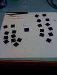
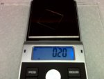
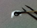
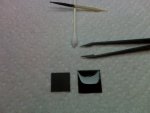
1) I took a microscope slide coverglass and coated it with a carbon film coating. Each slip is 0.14 grams and when coated, they weigh 0.22 grams. I did a bunch and they all came out the same weight. We now have a known mass that can easily be repeated.

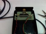
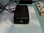
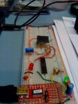
2) I built an extremely accurate (0.02 degree Kelvin) IR thermometer. I've entered this into Instructables Technology microcontrollers contest: A PICAXE Infrared "logging" Thermometer
You can build one easily... code is open source and the part count is minimal.

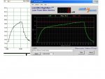
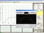
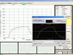
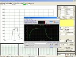
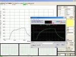
3) I put new batteries in my laser pens and charged all the rechargeable lasers. I ran a full suite of tests graphing the results on my LaserBee. I put in new batteries and recharged and ran another set of tests on the painted coverslips measuring the temperature rise above the room temp. The output of the PIC directly fed into the PC and graphed. Just like with the LPM, all tests ran a minimum of 30 seconds or until the laser reached peak power after which time I turned the laser off and allowed the power/temp readings to return to the starting point of 0.000 or room ambient.

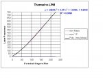
4) I stuck all of the information into Excel, plotted it, and ran a regression to fit the best curve. My R-squared value is 0.9998, which indicates a very good fit.

Results:
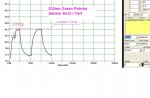
For a given target with a high emissivity (close to 1.0) and in a controlled environment (stable room temperature, minimum drafts, etc.) the temperature rise above ambient is directly related to the optical power of the laser. See graph.

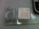
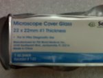
I'll try and elaborate more in the next post. The glass coverslips were obtained from eBay. The carbon coating is a proprietary carbon nanotube product; I am attempting to obtain permission from the manufacturer to reference the product by commercial name. If you wish to experiment, use several coats of high-temperature flat black paint on both sides of the glass coverslip... you must be very consistent if you intend on being able to compare results with others. I recommend "baking" the painted coverslips to remove all of the solvents... I use the kitchen oven set at 350 (but only after the wife has left for work) - typical cook time about 30 minutes.

Errors:
For 30mw to 750mw, the maximum error was 10% for the 50mw greenie. The 5mw Red was not included in the curve fit. At 200mw for both IR and Red, the error was 0% and for the Artic (445nm) at 750mw the error is 3%. Again, the LaserBee USB 2.5W unit (2% or better) is the measuring stick in this experiment.

- Ray
 

Attachments

  • Thermal rise vs LPM.JPG
    Thermal rise vs LPM.JPG
    47.1 KB · Views: 377
  • Lasers by Power.JPG
    Lasers by Power.JPG
    31.9 KB · Views: 362
  • IR 200mw 808nm O-Like Pointer.JPG
    IR 200mw 808nm O-Like Pointer.JPG
    64.4 KB · Views: 362
  • Red 200mw 660nm O-Like Pointer.JPG
    Red 200mw 660nm O-Like Pointer.JPG
    64.7 KB · Views: 353
  • Green 30mw 532nm pointer.JPG
    Green 30mw 532nm pointer.JPG
    64.9 KB · Views: 324
  • Green 50mw 532 O-Like Pointer.JPG
    Green 50mw 532 O-Like Pointer.JPG
    64.2 KB · Views: 296
  • Artic 1W 445nm Wicked Laser.JPG
    Artic 1W 445nm Wicked Laser.JPG
    64.5 KB · Views: 389
  • Violet 30mw 405nm O-Like Pointer.JPG
    Violet 30mw 405nm O-Like Pointer.JPG
    64.6 KB · Views: 296
Last edited:


Trevor

0
Joined
Jul 17, 2009
Messages
4,386
Points
113
Re: In the H.E.A.T of the light (coherent)

This is wicked cool. Looking forward to the second installment! :D

-Trevor
 
Joined
Jun 19, 2010
Messages
1,487
Points
63
Re: In the H.E.A.T of the light (coherent)

Thank you for this very well put introduction!

I am a complete novice to electronics, laser, physics, and all those sciencie things. I am, though on my way to learning a thing or two, thanks to threads like yours.

I will follow with close attention and as much comprehension as I can muster.:beer:
 
Joined
Jan 27, 2011
Messages
701
Points
0
Re: In the H.E.A.T of the light (coherent)

This is very neat :beer:

I'm subscribed :)
 
Joined
Sep 20, 2008
Messages
17,622
Points
113
Re: In the H.E.A.T of the light (coherent)

Interesting info RayBurne...:gj:
I'll be reading more as you post it....


Jerry
 
Joined
Jun 9, 2011
Messages
46
Points
0
PART TWO

Exploring the technology:
In the screen-shots in part one, I have provide both the thermal plot and the LPM plot and I have adjusted the two images such that "0" is horizontal and the max-power for the particular is also horizontal across the two graphs. This helps to compare the curves. It can be seen from each individual test that there are similarities: the up-ramp, the peak, the down-ramp (laser off.)

The up-ramp is the thermal mass coming up to temperature. In the case of the LPM, it is the thermopile and in the case of the carbon-covered glass, it is essentially the combined mass of the two. If you have an electrical background, think of the thermal mass as being a capacitor, it is charged to "room ambient energy" and then the laser photon energy adds to that charge (convection, conduction, and radiance "bleeds" the charge to create a time-period similar to a typical RC curve) raising the energy level until the system reaches equilibrium- at this point, the graph essentially goes flat-line.

The down-ramp is simply the system exchanging heat to the environment. In the case of the LPM, a nice, heavy heatsink is responsible for dissipating the heat to the environment. In the case of the glass slide, the three fundamental heat loss mechanisms come into play: conduction, convection, and radiation (just the same as the LPM but in different ratios.)

Former member Warske presented a very similar experiment over 2 years ago. His technique used a small piece of aluminum foil, some black spray paint, and one of the point-n-click inexpensive IR thermometers. Some rather simple math suggested the conversion of temperature to optical power. Unfortunately, there was no proof offered, no explanation of the math, and no artifacts mapped directly to a LPM to prove the theory.

Our testing utilizes a microprocessor (PIC) controlled circuit that interrogates an extremely sensitive IR thermometer MLX90614 manufactured by Melexis once per second. The MLX90614 has dual-thermopiles in the IC can and a series of optical and electrical filters which make this device accurate to 0.02 degree K (or degree Celsius.) One thermopile targets the external field of view and the other thermopile records the internal temperature of the IC. In this manner, the unit will provide accurate readings even when the ambient temperature changes - hence no zeroing required.

The software in the PIC does very little math, essentially I rewrote the original code of Professor Anderson and removed much of the math; rather, I elected to do the math externally in the PC software. In our case, we are using a free package from Selmaware called StampPlot Pro. You can see some of the calculations in the screen shots. A more detailed explanation is available in my technology article in Instructables: A PICAXE Infrared "logging" Thermometer

In contemplating the target, assume that the perfect target would be a blackbody... all of the laser energy at any wavelength would be absorbed and re-radiated in IR such that the sensor would "observe" and measure that energy. Unfortunately, the real world gets in the way of perfect and we have conduction and convection that saps away some of the energy that we wish to be converted to radiant IR for detection. Additionally, our black carbon nanotube coating is not a perfect absorber, there is some reflection off the surface. However, our tests show a very good correlation between the IR temperature and our math for converting to mw of optical energy. How is this so?

Essentially, I cheated. Remember, I used the LPM on each laser and then matched the graphs. I did this for 808nm IR and for 405nm Violet and all in between. So, I calibrated the thermal sensor with the LPM. In this chicken-egg paradox, the egg came first. Had I not had a LPM handy, I would have had to resort to all manner of heat transfer equations to work out a solution. As it is, I'm using a 3-order polynomial equations to create the trend line in Excel. What is important is that once the math is known, anyone can reproduce the experiment anywhere and have reasonable results. This is not to say that such a crude instrument could replace a LPM; rather, it is just another instrument for experimenters. For example, if you are mixing your own super-black velvet paint for use as an optical absorber you are very unlikely to want to apply the test paint to your expensive LPM. You would, however, have little concern for applying the paint to a nickel-worth glass cover slip and blasting away with your laser. If your current batch of paint is better than in the past, then plotting the results of the temperature rise and maximum temperature will quickly show the positive results. If the graph shows a slower rise and/or a lower temperature, it is time to go back to the old formula.

The purpose of this article is to get us all thinking about how we could use a new tool, an inexpensive an versatile little device. All that is necessary is that everyone of us use the exact same target glass slip so that the mass is identical, the x, y, and z dimensions are identical. Then if we coat it with the same stuff to the same specifications, we have a common tool for experimenting. This is no different than what Warske was suggesting two years ago... BUT this time the technology is better and it can be proven that the technique works reasonably well over a wide range of powers and wavelengths.

The photo in this post shows the PIC protoboard with the IR thermometer and the glass cover slip target suspended over the sensor by 1/2 inch. Note that the target is mounted horizontal in these tests, a completely new set of tests using the LPM would be required if I were to orient the target to be vertical since orientation generally affects the heat dissipation from convection (air-target interface and associated air currents.) A friend is building me a circuit board for a more permanent unit and the target will be mounted vertical, so I will post new information and confirm the change noted. The conduction component is the contact between the cover slip and the fancy straight pin that I superglued to one corner of the slip... straight pins work great for sticking in the little connecting holes of the protoboard and I just used my old wire cutters to trim the end until I got the height correct.

More later. Spec sheet for IR sensor for the curious: MLX90614 is a digital thermopile based non-contact infrared thermometer in a TO39 housing

For the scientists and physicists and advance science students out there who want to "play" with a computer simulation, a rather good model is available for Excel on the PC: Animated Heat Transfer Modeling for the Average Joe – part #1 « Excel Unusual


- Ray

-End Part 2-
 

Attachments

  • Thermometer-photo.jpg
    Thermometer-photo.jpg
    35.6 KB · Views: 338
Last edited:
Joined
Apr 28, 2009
Messages
2,416
Points
63
:pop: Very detailed and succinct explanation. It makes good reading for those interested in laser physics. I vote for a sticky! :beer: You remind me of another laser physicist here by the name of FrothyChimp.
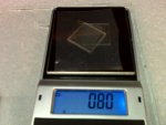
 
Last edited:
Joined
Jan 27, 2011
Messages
701
Points
0
This is a really great read! I'm haven't dealt with lasers on a phyics base before this is very interesting.
 
Joined
Jun 9, 2011
Messages
46
Points
0
PART THREE

Our target is made of thin glass cover slips, the little rectangle glass that fits over a microscope slide to hold the viewing object in place. I use glass because it is an excellent thermal conductor, the slips are machined to be all the same physical size in all dimensions, and the coating I am using adheres very well to glass. I have coated both sides of the glass with 3 drops of carbon nanotube lacquer. I have broken a few slips messing around with them but never because of the high temperatures, sometimes approaching 400F on the IR thermometer, so spot temperatures may be much higher. The coating is tough, withstands direct pinpoint targeting at 200mw+ without punching-through the film, laser "burns" seem to have no effect on absorption, and testing (my testing) has shown the product to be optically flat across the major hobby laser spectrum. What's the name of this magic stuff? Here is the deal... I'm misusing the product label instructions since the product is marketed for an entirely different purpose. While my testing has shown no ill effects, my friend who has a legal mind (is this an example of an oxymoron?) has warned me against posting the product name unless the manufacturer approves first. So far, they are mum... silent, non-responsive. Please understand as I try to work through this issue. I would feel terrible if for some crazy reason one of these glass slides should shatter violently due to the internal stress in the glass caused by thermal gradients. I would feel even worst if someone got hurt. So, the product goes unnamed at present and I'll just suggest a good flat-black paint for your experiments. But, please wear your laser eye protection since this will also protect you should the glass slip shatter unexpectedly. SAFETY FIRST>

My first glass slips came from eBay and are pictured in the first two pictures attached to this message. The quality is adequate but I paid like way too much to have these things shipped. I've ordered and received from a medical supply company that services doctor offices here in Atlanta a box of slips. They are pictured in the third and fourth picture. Guess what, the old and new slides are different sizes, therefore we have different target mass. Will it matter? Ah, another set of experiments are planned to make that determination.

You will also see in the pictures attached that I'm using 5-drops of lacquer on the new slides because they have a larger area and I do not wish for the coating to be too thin. This will introduce yet another variable in the next experiment. The lacquer is dropped onto the slip from a toothpick which has been dipped into the carbon product. Gravity will provide the droplets, if not, you have not dipped the toothpick deep enough to pick up sufficient lacquer. After the last drop, do not wipe the toothpick but use it to gently "pull" the puddled liquid from the center of the slip toward the sides. Then use the end of the toothpick to persuade the lacquer to flow to the edge of the slip making sure that the entire surface of the slip is coated with the liquid. Because we started from the center outward, there is a tendency for more material to be in the center - this is OK since we target the center with the laser.

The lacquer must dry overnight, then the reverse side must be done. Use the same quantity of fluid, 5-drops, and allow to dry for 12 hours. After both sides are coated, it is a good time to bake in the oven for 30 or so minutes at 350F to ensure that the solvent is fully expelled from the carbon film.

We now have a target. I used a weebit of SuperGlue and a straight pin with the head glued to one corner for support, but you can deviate. Share the knowledge should you find a good, easy way to do this. I'm going to have a new thermometer built soon as a permanent addition to the desk and I will be using the targets in vertical fashion instead of the horizontal configuration that I'm now using. I'm thinking about using super-fine hairwire and passing it across the top and across the bottom of the slip and then using something like an oversized color slide carrier (remember 35mm slides?) to support the wires with the slip suspended in the central portion. At least, that is my thought at the moment, but I reserve the right to deviate during the build :crackup:

Please exercise extreme caution in your experiments. The black-coated glass slips become very hot and the cool-down takes as much as 30 seconds. You may receive a severe burn if you touch the target before it cools to room temperature.

- Ray

-End Part 3-
Note: This is about the end of any formal input with the exception that I will post the results of my testing with the new, larger glass cover slips. If possible, I will update you on the carbon nanotube coating. If anyone wishes to have me process a specific experiment, I will entertain the idea. Thanks to all that had good things to say; good vibes most welcome.
 

Attachments

  • Old eBay Cover Slips weight (x3).jpg
    Old eBay Cover Slips weight (x3).jpg
    61.4 KB · Views: 322
  • Old eBay Cover Slips.jpg
    Old eBay Cover Slips.jpg
    64.7 KB · Views: 319
  • New Cover Slips.jpg
    New Cover Slips.jpg
    64 KB · Views: 286
  • New Cover Slip weight.jpg
    New Cover Slip weight.jpg
    61.8 KB · Views: 336
  • New Cover Slip Prepare 5-drops.jpg
    New Cover Slip Prepare 5-drops.jpg
    64.8 KB · Views: 291
  • Old vs New (drying).jpg
    Old vs New (drying).jpg
    63.8 KB · Views: 293
Last edited:
Joined
Jul 3, 2009
Messages
332
Points
28
I remember that thread from a while back, and this is some good stuff. Im nowhere close to being on that level but I was able to follow along because you have the ability to explain and relate what your talking about so well.

I have always been big into science, I have read and seen a few shows that talked carbon nanotube technology and its uses which was neat for me because no one really talks about it. After reading this I felt compelled to see if I could find some for sale online and google doesn't give much lol.

I would love to pick your brain and ask tons of questions about various other things but I'll hold back. Great read and I will definitely stay tuned!

-Greg
 

HIMNL9

0
Joined
May 26, 2009
Messages
5,318
Points
0
May i give you a suggestion for improve the mount and efficence of your sensor assembly ?

I see you're usinf a single zone, 90 degrees aperture sensor ..... you can probably increase the efficence, sensibility and immunity from disturbs (including air currents), closing the sensor and the glass plate in a small plastic tube ..... get a tube that you know is opaque to long IR, that have the internal diameter a slightly bit (0.5 to 1 mm) larger to the diagonal of your glass plate, then glue the plate inside the tube for the corner tips using 4 small points of silicone (this reduce to minimum possible the thermal draw from the plate due to the suspension), keeping the plate in the middle of the tube lenght, then place the sensor at a distance that grant you to cover the more possible surface of the glass plate, considering the 90 degrees aperture.

This may help insulating the assembly sensor/plate from external unwanted radiant sources, and prevent errors due to airflows, also self-convected flows ..... just as idea ;)
 
Joined
Jun 9, 2011
Messages
46
Points
0
HIMNL9: Of course you may make a suggestion... I may be an old-fart but I'm always learning something new. The idea is excellent, I've been experimenting with different ideas. In the first 'boxed' phototype, I had magnets glued inside the front face of the unit and had an assembly that held the target in front of the sensor... this was affixed with magnets too, so I could just 'snap' it on. I'm wanting to use the IR thermometer for several projects and being able to convert it quickly for laser play is a nice feature. In this configuration, I had a piece of PVC cut to surround the slip and thereby do a little damping of the target. If I could find some wideband AR coated quartz windows :)

- Ray
 
Last edited:
Joined
Jun 9, 2011
Messages
46
Points
0
PART FOUR (Edited 20110702 - Free target slips all gone!)

Target position, Vertical or Horizontal, Experimental results below:

I did three tests today with the target used in Part One. I used a 5mw Red, a 30mw Green, and a 30mw Violet (405nm) and all of the results were identical. I'm posting the 30mw Green as the baseline.

Short story, I can detect no appreciable difference with the target mounted horizontal or with the target mounted vertical. Once my circuit board is completed the IR sensor will be pointing out of the minibox in horizontal fashion as shown in the Instructables article. I'll try and incorporate the ideas of HIMNL9 for mounting the front target (which will be vertical.)

Drafts aside, the similar results for position mounting of the target suggests that air-currents caused by convection around the target are minimal and do not interfere with the IR readings. I must admit that I was a bit surprised with this testing since I fully expected at least a 5% to 10% difference. My belief at this time is that eddy air currents are forming but because the IR sensor is averaging the field-of-view of the target, that the effect is minimized by the sensor design. Attributing also to the minimization is that the glass slip is an excellent thermal conductor and both sides are coated with the black carbon lacquer, so front to rear thermal gradients are minimum. I'm open to other suggestions.

- End Part 4-


- Ray
 

Attachments

  • Horz Vs Vert.jpg
    Horz Vs Vert.jpg
    64.3 KB · Views: 287
  • More detectors.jpg
    More detectors.jpg
    63 KB · Views: 273
Last edited:
Joined
Jun 9, 2011
Messages
46
Points
0
PART FIVE

Test results on new glass slip, 22mm x 22mm #1 thickness from Select, PSS World Medical, Inc.

As I explained earlier, the heart of experimentation is to be able to have repeatable results... in my lab or in yours. Using the Chinese glass slips was a good start, but my source vanished from the Internet. I'm sure he has reinvented his identify elsewhere, but I need to be able to have an open supplier for these in the U.S. just to make life easier for anyone wanting to duplicate the results.

I got my digital recording thermometer back today from my friend who was kind enough to take my prototype perf board and move the components onto a little custom PC board. He's good at things like this and even better, he does it often enough that he had the scrap PC board and the chemistry in his basement - no cost to me:D

I ran a few tests on the unit and it compared perfectly with old results. So, I grabbed my new enlarged glass slip coated with the nanotube carbon lacquer and performed a test using both the LaserBee USB LPM and my optical LPM. The results are show below. I plan to conduct more tests over the next week using various power lasers and IR to UV in the bandwidth. Sometime after those tests, I'll load everything into Excel and run a trendline for you guys with the equations and the R^2 factor.

Those wanting to build one of these PC logging thermomenters can follow RayBurne on Instructables for the basics; the link is up in posting #1. The parts costs will run you about $22 if you already have a solderless breadboard, resistors, 5V regulators, etc. If not, you can get into PIC programming and electronics and build out your own circuit for under $50. A recording IR thermomenter can be a useful item not only for experimentation but for identifying if your AC is working correctly, if you have hot-spots around windows/doors (cold-spots in the Winter!)

Whatever you do, have fun, and please be safe.

- Ray

-- End Part 5 --

Simplified repost: http://www.instructables.com/id/LASER-HEAT/
 

Attachments

  • New Cover Slip weight.jpg
    New Cover Slip weight.jpg
    61.8 KB · Views: 267
  • New Optical Slip - LPM Compare.JPG
    New Optical Slip - LPM Compare.JPG
    64.8 KB · Views: 281
  • IR Recording Thermometer.jpg
    IR Recording Thermometer.jpg
    60.9 KB · Views: 316
  • Completed Logging IR Thermometer.jpg
    Completed Logging IR Thermometer.jpg
    62 KB · Views: 282
Last edited:

AUS

0
Joined
Apr 12, 2012
Messages
565
Points
28
Very interesting. Like your Picaxe thermometer as well. Reminds me of an RF "calorometer" where you use lots of lossy coax cable as a dummy load in ice water and measure the temperature rise to calculate power.

First time poster, long time reader...


Top