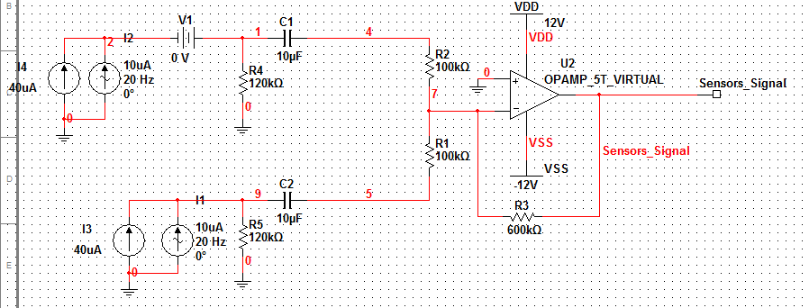
That will prevent electrical saturation but not optical saturation. I used a similar scheme for my AM laser transceiver which used a 650nm centered photodiode as a receiver, and I noticed that the gain was reduced as ambient light level increased, because even though electrical side saturation was prevented, the quiescent operating point of the PD coincided with the ambient light level. Thus the peak-to-peak profile of the signal after the high-pass/DC-blocking section was inversely proportional to the ambient light level. Being simple audio production it was not a major issue, but if the P-P profile gets reduced below threshold levels for your signal detection/timing circuit you'll need greater amplification to restore functionality. You might be able to put in some kind of automatic gain control, but I have no knowledge of such implementation methods.
What exactly is and is not acceptable in terms of S/N ratio will be largely based on what you're using to detect the presence of a bounce signal. Unfortunately I don't have any experience with such circuits (I tend to work with simple TTL voltage controlled stuff when it comes to pulse trains and switching) so I can't really advise on it.
Try assuming a maximum range of current for your PT current source simulation and then varying the noise sources intensity to occupy an increasingly larger portion of the maximum range. This will more closely approximate optical saturation.
Example: if the PT can source a maximum of 100uA, try having the DC source at 50uA for moderate ambient light, and then the AC source at 20uA. Now add in a 1MHz DC Pulse source (or AC if you can't do DC pulse) that is the data from your PT and set it to be the remaining 30uA. Observe the outputs. Repeat while varying the currents of the three sources (DC-ambient, AC-noise, DC/AC-signal) while remembering to make sure all the currents add up to an assumed maximum current output from a real-world PT.


