Welcome to Laser Pointer Forums - discuss green laser pointers, blue laser pointers, and all types of lasers

LPF Donation via Stripe | LPF Donation - Other Methods

Links below open in new window

ArcticMyst Security by Avery

How to build a blu ray in a flashlight

Joined
Apr 28, 2009
Messages
111
Points
0
On ebay, radioshack or google it.

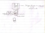
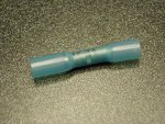
Maybe theres a better type of connector than using a butt connector. I do not know what can else be used instead of them. I understand what you want, you just want sometype of connector to prevent soldering and to exchange just the diode every time you want to use a different driver, host, etc.
 

Attachments

  • butt_connector2.jpg
    butt_connector2.jpg
    78.5 KB · Views: 1,565
Last edited:


k1kb0t

0
Joined
May 12, 2009
Messages
454
Points
0
Most people solder the leads to make sure they don't have a bad connection, which can kill the diode. If the connection is bad, the driver cap will charge and discharge, killing it.

Jon
 

lazer

0
Joined
Dec 21, 2008
Messages
361
Points
0
I want a contact point that makes contact with the batteries in the battery chamber. I would then solder that contact point thing to the driver. Sorry I dont know a better way to describe it. Ill make a diagram later on today.
 
Joined
May 6, 2009
Messages
194
Points
0
Most people solder the leads to make sure they don't have a bad connection, which can kill the diode. If the connection is bad, the driver cap will charge and discharge, killing it.

Jon

I did this the other day, Jon is sooo right about this point. Watch it, I'm positive my diode was fine before I attempted this manuever. :(
 

lazer

0
Joined
Dec 21, 2008
Messages
361
Points
0
I want to solder a wire from the driver to the battery contact in the battery chamber. I want something to use as the battery contact so I wouldnt hae to solder on the batteries. I will solder the diode to the driver and the driver to the switch.
 
Joined
Apr 28, 2009
Messages
111
Points
0
what i recommend first is to put a blob of solder on each terminal of the driver to then melt that blob and stick the pins or connections into the blob of solder.
 

lazer

0
Joined
Dec 21, 2008
Messages
361
Points
0
Thats what I did. I just need something to make contact with the battteries that I will solder to the contact of the driver. I dont want the driver making direct contact with the batteries because it might be damaged.
 
Joined
Apr 28, 2009
Messages
111
Points
0
you should put some pictures of your flashlight and connections, driver, etc , so we can know how to help you in a better way
 
Joined
Jul 24, 2007
Messages
2,749
Points
0
If your driver fits inside the Aixiz module you need an insulator and a brass washer or a drilled out screw, this will become your positive contact.

If you look at the second photo you will see that the back of the Aixiz is drilled out, this is to make sure that the driver does not get twisted as the back is screwed on. I solder the neg wire from the driver to the Aixiz module (ignore the switch, this was for a side button conversion). The positive wire from the driver goes through the insulator and is soldered to the brass washer, this is the pos contact that touches the battery.
The first photo shows how it looks when assembled (drawing doesn't show the neg wire as this was for a red build).

Hopw that helps

Regards rog8811
 

Attachments

  • module02.jpg
    module02.jpg
    65.7 KB · Views: 447
  • 803T-02.jpg
    803T-02.jpg
    79.2 KB · Views: 201
Last edited:

lazer

0
Joined
Dec 21, 2008
Messages
361
Points
0
Yes that helps alot thanks. Now I can build a 6x bluray. :)
 
Last edited:
Joined
Apr 28, 2009
Messages
111
Points
0
lazer show some pictures when you are done with your laser, to see if everything went well
 

lazer

0
Joined
Dec 21, 2008
Messages
361
Points
0
Do you have to use the case negative pin on the diode to put it in a flashlight? I plan to wire the it like the picture attached. Sorry it is hand drawn.
 

Attachments

  • Laser Diode w Driver.jpg
    Laser Diode w Driver.jpg
    43.8 KB · Views: 171
Joined
Apr 28, 2009
Messages
111
Points
0
in the picture the negative is attached to what? if its connected to the heatsink or module its fine. The only thing you have to becareful is that the part you are connecting the negative connection to a ground should not be insulated(for example: Paint, rubber).

You just need the negative connection go to any ground, just dont let positive and negative connections touch each other because will create a short circuit.

Look. if the negative wire is not connected to the diode case it haves to go to battery negative or other ground.

if you connect negative diode pin to case pin you just have to connect it to the driver negative.

If im wrong , some one correct me
 
Last edited:

lazer

0
Joined
Dec 21, 2008
Messages
361
Points
0
in the picture the negative is attached to what?
if you connect negative diode pin to case pin you just have to connect it to the driver negative.

The negative is connected to the module underneath the positive contact insulator.

Ill use the case pin to diode negative technique but do I connect the diode negative and case pin to the driver input negative or driver output negative?
 

lazer

0
Joined
Dec 21, 2008
Messages
361
Points
0
Got it. do I need to have a negative input to the driver from the batteries? I assume I do.


Top