Welcome to Laser Pointer Forums - discuss green laser pointers, blue laser pointers, and all types of lasers

LPF Donation via Stripe | LPF Donation - Other Methods

Links below open in new window

ArcticMyst Security by Avery

How do I center a C-mount diode?

Joined
Sep 27, 2009
Messages
155
Points
0
Hello,
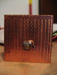
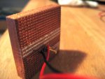
I have gotten a couple c-mounts in the 4 whatt range, and I'd like to build a heatsink out of copper for them. My cnc router will do the job, but I need to do the drawing job, with the holes placement (mounting hole, and negative lead pass through hole). My question is how do I make sure the actual chip is centered? Is the beam emitted from the top center or from the top right?

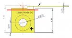
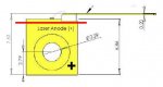
Here is a diagram of a similar c-mount.
 

Attachments

  • C-Mount Schematic.JPG
    C-Mount Schematic.JPG
    10.4 KB · Views: 830


Joined
Jun 19, 2009
Messages
2,710
Points
0
I'm almost 100% sure that it comes from the center of the die, and covers the entire length of the die's face (width wise).


Edit: What he said
 
Last edited:

HIMNL9

0
Joined
May 26, 2009
Messages
5,318
Points
0
Ofcourse, the beam came from the chip, and have the center in the chip center, the shape oval as showed, and the polarization planes in line with the chip axis

attachment.php


Is right for this reason that they gives you also the quote relative to the chip center from the base (that 6.86 in your draw), so you can use it and the center hole quote for draw your heatsinks with the chip already centered in the right position ;)
 

Attachments

  • C-Mount Schematic 2.JPG
    C-Mount Schematic 2.JPG
    45.1 KB · Views: 827
Joined
Sep 27, 2009
Messages
155
Points
0
Thanks,
do you think it would be a good idea to carve a pocket into the heatsink so the diode fits flush in there and there is more contact area on the sides to cool it?
Also I read that the heatsink should not go above the red line in the drawing because the reflections can damage the back side of the facet area. Do you recommend this or could I just paint that portion black so there are no reflections?
 

HIMNL9

0
Joined
May 26, 2009
Messages
5,318
Points
0
As far as i've seen til now, C-mount assemblies are flat all the space, regardless for the red line limits or not, so i really don't know ..... maybe it's referred to mirror finished surfaces, but a normal, matte heatsink, i doubt it can cause you problems.

About the "pocket" i suggest you to not use this system, at least if you're not 100% sure that the rest of the mounting parts (holders, lenses) are perfectly aligned with the center of the chip ..... better that you keep a little bit of possibility to move it, just in case ..... and no, probably the heatsinking will not be improved from this.

Can be more helpful some conductive paste or mix, or also (but is more difficult to find it as hobby level) a very thin foil of indium, for use as "gasket" between the c-mount and the heatsink (indium conduct heat very well, and is soft, so it self-adapt to the surfaces, when pressed in them) ..... anyway, for the few c-mounts that i've used til now, i used the same paste that is usually on P4 heatsinks, with good results (the grey one, it don't spill like the white silicone grease based)
 
Joined
Feb 21, 2008
Messages
1,056
Points
0
It is not recommended to use thermal paste when mounting c-mounts to heatsinks. Temperature changes can cause the thermal paste to migrate, and it will destroy the coatings on the output facet of the die if it travels there. Indium foil is no problem. The thick gray P4 paste is probably OK, use it sparingly. As the die on a c-mount is exposed, your mount should also seal well to prevent any dust, dirt, smoke particles or other detritus from landing on the output facet, which would kill the diode.
 
Joined
Sep 27, 2009
Messages
155
Points
0
Ok, this is my progress so far.
I made the heatsink out of thick copper. The size is 40mmx40mmx10mm it was cut totally with my cnc router machine, the original piece was 50x80x12mm, I first surfaced the pice of copper, and it came out very flat, reasonably shiny, I cut it with a 3mm router bit with 3 flutes, and it took a while. I also made the 2 holes, one for securing the diode, the other for the negative wire.

I fired up the laser and it's scary powerful, of course you can't see anything at all, like with 808nm (this is 915nm), but through a camera the beam shows like baby blue, and its amazingly bright, I only gave it 2 amps so far, and it's capable of up to 8 Amps.
I am going to have trouble collimating this sucker. It shoots quite a bit upwards, like 7-8°, and focusing it through the camera is not exactly easy.
Will keep you updated. These are the photos so far.
 

Attachments

  • 4W.JPG
    4W.JPG
    64.6 KB · Views: 382
  • 4Wback.JPG
    4Wback.JPG
    141.8 KB · Views: 390
Joined
Feb 21, 2008
Messages
1,056
Points
0
Your heatsink came out nicely! Now you need to add some way of holding optics, so that you can experiment with collimation to a burning point. If you can get an aixiz lens a couple of mm's from the diode, you may get a burning point a few inches in front of the laser. For various lenses, www.surplusshed.com is handy, they usually have cylindrical lenses, which come in handy with these multimode diodes. Save lenses out of any old scrap you find, they come in handy.


Top