Hi, well first off, "ignorance" depends on point of view.
You do not know, and you are asking about it. That's good. Ignorant man ignores his ignorance, IMHO.
Next, well, LM317 is called a voltage regulator, because it is it's primary use, but this is how it works:
It'll supply some voltage reference between it's pins OUT and ADJ, and according of resistance it will supply the constant current.
Now, let's say that you use a constant current of 1A to power nothing more than one 5 ohm resistor.
Now, you have 1 Amp, and 5 ohms, do yo know ohms law?
It says :
Voltage = Current x Resistance (this formula nad many it's derivations are widely used).
Now, that means you have exactly the 5 Volts of potential difference on pins of the resistor.
That means that , whatever you hook up in parallel with that resistor, it will be powered by constant voltage of 5V (ideal for example, IC and MCUs which work on 5V).
Now , what we do is not use the final resistor at all, but use the constant current to power out precious laser diodes (speaking of which, your avatar is depressing ...

)
Next, 1W 808nm diodes require 1.25 A, which is achievable with LM317 and 1 ohm resistor as current setter.
However, maximum rating for LM317 in TO220 case is 1.5 A.
2W diodes would require double than 1W, and hence, LM317 is out of picture.
If you need more power (one always needs more power!

), you can use the LM350. It is used identically as LM317, same Vref and everything, except it can supply up to 3 A!
The battery pictured few posts up is my "testing" 18650 cell, it's naked - I stripped it off it's regulation circuit and heatshrink tubing, and it's entire surface acts as negative connection except the positive pole, obviously.
I can use to to test green modules or such drivers and stuff, because of large surface of negative connection it's easier to use with springs and alligator clips maybe, then normal batteries.
In any way, lithium ion cells such as this one have a surface charge of 4.2 V when fully charged, and they discharge until 2.8 V.
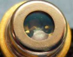
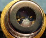
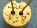
I always keep it at full charge to power various stuff, like 1W 9mm diode seen in pictures (forgive very sloppy setup, no module or focusing, I soldered it real quick so I can take pics and present my point that driver OP posted is a wayste of components, rudely put).
I think that answers all your questions for now, if you have any more questions about anything at all, do not be afraid to shoot me a PM (personal message) and ask away! I have a lot of free time on my hands
")
EDIT = Oh, how hot it gets? Considering it's underpowered by therms of voltage (4V is not enough, 2.5 V drop of driver and 2 V diode voltage, I'm 0.5 V short), I can' give accurate anwer, but let's say that you supply exactly the needed voltage at 1A, total power dissipation is around 2.5W, add more watts with more volts supplied.
Driver would produce 2.5 W, and diode around 1W
Ironic, driver needs more cooling than the diode.


")