Welcome to Laser Pointer Forums - discuss green laser pointers, blue laser pointers, and all types of lasers

Buy Site Supporter Role (remove some ads) | LPF Donations

Links below open in new window

FrozenGate by Avery

Help with pen host build

Joined
Apr 21, 2016
Messages
24
Points
3
Hi there!

I'm brand new to LPF, though I've been browsing for a little while. My collection of lasers has been growing a lot, and lately I've really got an itch to put one together. I've got a number of packaged laser diodes, and most of them I've already installed in a module. A few already have G2 lenses and drivers on them (bought a few from DTR recently).

I also recently bought a couple pen hosts and switch PCB's from laser66, and I cannot for the life of me figure out how to put this together (even after lurking the boards a while). Does anyone have any input or recommendations on how I go about that?

I'm very experienced soldering and am finishing up my bachelor's in EE, so you don't need to be too vague! Any input is greatly appreciated.

Thanks very much!


Another EE major!:beer:

Just look around the site for people's builds. Styropyro has a good video on it too. There are contacts on the switch PCB that you need to wire up to your driver.


Here's the first one I found by searching:
http://laserpointerforums.com/f65/pltb-450b-laser66-build-led-indicator-96212.html
Might be a little extra complicated, but it'll give you an idea of how to get it together.

Edit: For searching, keywords to look for are: Laser66, chrome pen host, leadlight. Pman's posts are usually very helpful.
 
Last edited:
Hey, Life: I checked through your entire post history and found THIS one (is this right?)

If so, I might be missing the answer to my question -- I'm still not sure how to wire up the PCB. I spent some time with my multimeter earlier and trying to figure out where these pads connect, but I'm seriously having trouble finding a usable path with the switch in it.
 
hi,'
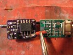
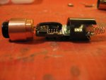
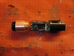
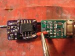
No thats not my build that's The amazing Pmans build..This is my build buddy.. The Case pin is used to connect with the Neg- power in on the driver. and the Pos+ to the driver power is the red wire connecting to the PC board. ok first of all use some arctic Alumina epoxy to connect the PC and the driver together to make it easier to make the solder connections. let the epoxy dry for a few hours first. then solder your diode and driver wires on. When you slide the assembly into the host strip a piece of wire and wedge in between the Copper module and the host white pushing it in till it's flush with the front of the host. this will keep it snug fitting for grounding. just make sure when you alighn the components there straight and true so when you glue the button on it's straight. hope this will clarify the process Pal.

rich:)
 

Attachments

  • IMG_1407.JPG
    IMG_1407.JPG
    196.3 KB · Views: 77
  • IMG_1397.JPG
    IMG_1397.JPG
    145.1 KB · Views: 57
  • IMG_1396.JPG
    IMG_1396.JPG
    184.4 KB · Views: 57
Last edited:
@Rivem: I've been looking through the video and the post you linked to, but the issue I'm having in every single guide I see with the switch PCB is not showing the actual connection to the board. Those are still really great resources you've posted! Thank you!
 
@Rivem: I've been looking through the video and the post you linked to, but the issue I'm having in every single guide I see with the switch PCB is not showing the actual connection to the board. Those are still really great resources you've posted! Thank you!

No problem. I wasn't sure what your problem was initially, but Lifetime17's last post should help you a whole lot more.
 
Life: That's awesome! That's definitely putting me in the right direction. Any chance you can elaborate on what else you did here? Did you tie the case pin to something? I can clearly see your V+ connection on the board but not much else. Very much appreciate anything else you can give me!
 
Life: That's awesome! That's definitely putting me in the right direction. Any chance you can elaborate on what else you did here? Did you tie the case pin to something? I can clearly see your V+ connection on the board but not much else. Very much appreciate anything else you can give me!

You only really need that one connection unless you're putting an LED indicator in. The other lead from your driver should usually just be connected directly to the case.
 
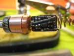
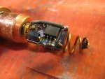
Hi The case pin Neg- is done this way easy stuff my man..this is just for reference to the case pin connection basically were the spring is here is were your Pc board will be epoxied instead..

Rich:)
 

Attachments

  • IMG_1549.JPG
    IMG_1549.JPG
    159.3 KB · Views: 52
Last edited:
Rivem: Any chance you can elaborate on that a bit? I'm trying to think about how that'll work -- is it through the battery? I'm still struggling with how this PCB is going to fit in the whole picture? And at that point if the batteries need to be in a particular orientation...
 
hi Kool,
look at this and look at the other and put them together Neg- and Pos+ connections

Rich:)
 

Attachments

  • IMG_1407.JPG
    IMG_1407.JPG
    196.3 KB · Views: 37
  • IMG_1241.JPG
    IMG_1241.JPG
    203.6 KB · Views: 52
koolksmart, he used the case pin to make the ground connection, or the negative connect, to the case of the host where the negative battery case will make connection at the end of the host. The positive connection is made through the extra PCB with a switch attached to turn it on and off. Some hosts come with a contact board already inside and you needn't worry about the switch PCB in that case. Hope this helps.
 
Hi Kool look at all my pics and just put it all together and you ready to lase on ..

Rich:)
 
Rivem: Any chance you can elaborate on that a bit? I'm trying to think about how that'll work -- is it through the battery? I'm still struggling with how this PCB is going to fit in the whole picture? And at that point if the batteries need to be in a particular orientation...

Paul and Life have it covered. Just remember that your case is the conductor for one side, and your diode is going to be electrically connected to it. The switch PCB is pretty much just for the switch and not much else. It interrupts one side of your circuit.
 
Just got it done, you two! Thanks so much for the help! Literally just finished my own first laser build AND it was a pen!! Ahh, I'm so stoked!


Back
Top