Welcome to Laser Pointer Forums - discuss green laser pointers, blue laser pointers, and all types of lasers

LPF Donation via Stripe | LPF Donation - Other Methods

Links below open in new window

ArcticMyst Security by Avery

Help with my "broken" DX laser

Joined
Jan 23, 2010
Messages
29
Points
0
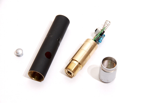
So I got a 5mW green laser from DealExtreme (http://www.dealextreme.com/details.dx/sku.91). After a few days it stopped working, after looking closely, the wire that attached to the frame had become disconnected. After barely touching it the wire fell out, broke off from the solder point.
So i FINALLY got the laser apart (pain in @$$). I really wish i had a good camera to take pics, but all i got is others pics, so please bear with me.
Here's what i got now, EXCEPT for the switch, this is a replacement switch someone installed, other than that it is exactly the same as i got now:
dx_laser_1.jpg

dx_laser_2.jpg

dx_laser_5.jpg


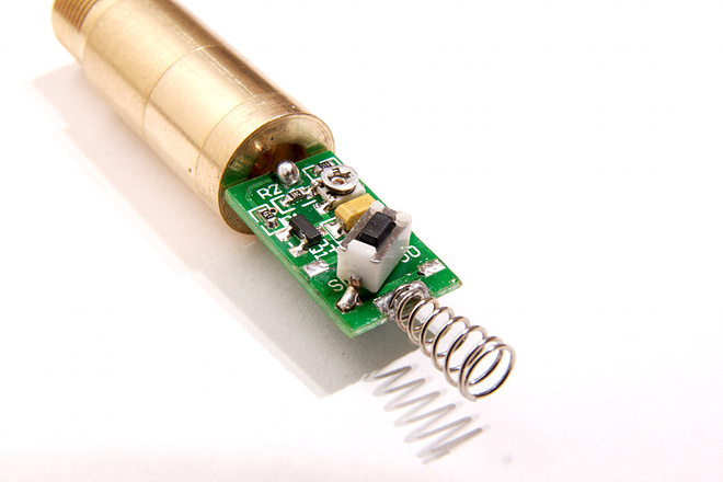
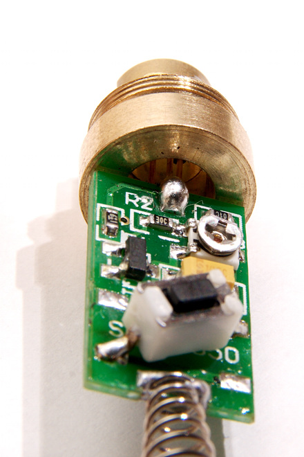
The button on there now has 4 leads on it and i can't tell which one the power wire broke off of. What i would really like to do is just bypass the button switch, and just run the laser off of a little DC converter (like an old cell phone charger).
Now i got a little electronics experience, but i suck at soldering, don't even have a soldering iron.
So should i follow the switch from the pictures and just place a wire over those pins or could mine be different wiring? everything else looks the same.

Sorry i don't got pics of mine. I'm just a noob with lasers but I'm loving them.


Joined
Oct 24, 2009
Messages
2,738
Points
63
Welcome to LPF. Enjoy your time with us here.

I would bypass the same two pins pictured in your bottom photo (of the replacement switch) Soldering will be required, maybe get a friend to do it.

However if you run a module like that one from a charger, You will need to put the entire module into a heat sink. (I assume since you said you know electronics, you know what a heat sink is)

Pointers / pens are made to be run in very short bursts and not meant to be left on for long periods, so it would over heat and die quickly.

mat.jpg


search.gif
 
Joined
Feb 5, 2008
Messages
6,252
Points
83
Hmm, has some soldering been redone on laser diode pins?
That big fat solder joint looks unprofessional and not overall good.

Anyway, the common 4pin switch works this way:
Unpressed:
PIN _____ PIN
____________
PIN _____ PIN


Pressed_
PIN _ ___PIN
___________
PIN______PIN (Cross sonnected)
Red lines are connections between pins.

So hard to tell from pictures here, but I believe replacing a 4pin switch with 2pin one does not require any kind of jumier wire.

I could be wrong though...
 

daguin

0
Joined
Mar 29, 2008
Messages
15,989
Points
113
Where did the wire attach to the "frame"? Where did it come from? Your pictures look like a perfectly good module. Does "other pics" mean that these pictures are NOT of your laser? NVM I just re-read the last sentence. These pictures of someone else's laser will only cause confusion. Delete them. Even a simple "paint" diagram of your laser would help more than pictures of something else.

You should very easily be able to tell which pads to jump on the switch with a DMM.

You should also be able to see where the wire broke off from by looking more carefully at the solder points. There will either be the end of the broken wire visible (if it broke) or there will be an "impression" of the wire in it (if it was a poor, cold solder joint).

Test the laser with your power supply first. Attach the positive lead to the case (the brass part) and the negative lead to the spring. Give it 3V and see what it does.

Peace,
dave
 
Joined
Jan 23, 2010
Messages
29
Points
0
Thanks photonaholic. I will definately be using a heatsink if i can get this working. I just want to make sure i can get it working first. Then i will get it on a heatsink. The casing it came in does not work too well as a heat sink anyway.
The spring on mine got destroyed, it's all bent up. That's why i was hoping to make this kind of like a lab laser. Something to just plug in to play with or make some kind of display. Unless someone has a better idea of what to do with it...........


Hmm, has some soldering been redone on laser diode pins?
That big fat solder joint looks unprofessional and not overall good.

Mine looks the same, big ball of solder on diode pin. These are DX lasers, cheaply made. Fortunately they are way overspec, i don't know how much but i can tell they are more than 5MW, i can slightly see beam during day.

Where did the wire attach to the "frame"? Where did it come from? Your pictures look like a perfectly good module. Does "other pics" mean that these pictures are NOT of your laser? NVM I just re-read the last sentence. These pictures of someone else's laser will only cause confusion. Delete them. Even a simple "paint" diagram of your laser would help more than pictures of something else.

You should very easily be able to tell which pads to jump on the switch with a DMM.

You should also be able to see where the wire broke off from by looking more carefully at the solder points. There will either be the end of the broken wire visible (if it broke) or there will be an "impression" of the wire in it (if it was a poor, cold solder joint).

Test the laser with your power supply first. Attach the positive lead to the case (the brass part) and the negative lead to the spring. Give it 3V and see what it does.

Peace,
dave

These are not photo's of MY laser (i don't have a good enough camera). But this is the EXACT same model and production as mine,the only difference is that switch. Mine is a black switch with 4 pins.
I have looked at hard as i can at all 4 solder points on the end of the circuit board and I can not see where the wire came from. They are all fine round solder points except for one, but it doesn't look like a wire was there, it just has a cut in the solder, like i scratched it when removing everying from pen casing.
 
Joined
Jan 23, 2010
Messages
29
Points
0
So I tried what you said, daguin. I connected 2xAAA batteries, positive to the laser housing, negative to the spring. No light came out, but after about 3 seconds, i noticed a little smoke and the wire got hot. I of course disconnected it right away, but I don't know what happened. I will try to check it out another time to see what happened. Hopefull its not burned out!!
 

Asherz

0
Joined
Jan 18, 2009
Messages
1,623
Points
0
How on earth did you manage to pull yours apart? I'm trying to get my 100mW one apart and I've tried everything, wrecked the host and the front still won't come off lol.
 
Joined
Jan 23, 2010
Messages
29
Points
0
It is extremely difficult to get it apart!!
The silver cap is pressed on, no glue. U just have to have it secured and slowly work the rest off. I destroyed the casing getting it out, and the silver cap is scratched up a lot.
Put the silver cap in a vise (between 2 pieces of wood and maybe some cloth if you don't want it scratched up). Then just work the other end off, maybe use a PVC "cheater" like tube to help shimmy it off. It will eventually come off.
I used vise grips and a pair of plyers, destroyed casing and scratched up the tip. If you do like i did, just make sure u aren't using the pliers below where the button is, otherwise u are just putting pressure on the laser module.


Top