Welcome to Laser Pointer Forums - discuss green laser pointers, blue laser pointers, and all types of lasers

LPF Donation via Stripe | LPF Donation - Other Methods

Links below open in new window

ArcticMyst Security by Avery

Help with 8a driver and load

Joined
Jan 29, 2014
Messages
12,031
Points
113
When I used to build high voltage power supplies, I had to make sure they were well matched when used in a full wave bridge, not sure about your use, I suspect they should be matched when paralleled for this use. You can buy 100 diodes and find that the voltage drops are all over the place within .1 to .05 VDC which can make a difference. I'd recommend using single larger current diodes. IDK, maybe manufacturers are doing better now, been a few decades since I looked into this. The problem is, which ever diode has the lower voltage drop will be the one more current flows through, defeating the reason you are paralleling them.
 
Last edited:


thehans

New member
Joined
Jul 22, 2019
Messages
4
Points
1
OK, I can do some matching. Do you know, if the voltage drop matches between two diodes at a low current, is that likely to indicate they will still match at higher currents?
In other words, if I match diodes very closely by my multimeter's Vf diode function at 1mA, will they still be matched at ~2.5A? Or would I need to measure each under appropriate load?
 
Joined
Jan 29, 2014
Messages
12,031
Points
113
Not sure, you might try at both low current as well as the higher expected shunt current through each diode too.
 

Spoomples

Member
Joined
Dec 8, 2018
Messages
54
Points
18
This may not be true for meters that aren't dirt-cheap, but my little LCR meter can be over 1V off of a diodes Vf at higher currents. You'll probably want to test it under load, and maybe take a gander at the datasheet.
 
Joined
Sep 20, 2013
Messages
17,254
Points
113
You are making this more complicated than it needs to be. Forget the diodes you already have. For DC purposes, you'll need to use 4 times the current rating for the diode to make sure they don't overheat and change significantly under load. My little dummy load has 10 amp rated rectifiers and it is only used at 2.5 amps maximum. Rectifiers are not expensive. Just buy some new ones rated at 10 amps each. Use short connections and leads as these will introduce voltage drops too.
 
Joined
Sep 12, 2007
Messages
9,399
Points
113
Since you are not using these as rectifiers it is important to get over rated diodes when using them in DC mode.


Mj0vKzF.gif


Paul is making shit up again. Ignore him.

It very clearly states on the datasheet that 3A is the rating, under the condition "Maximum average forward rectified current 0.5" (12.5 mm) lead length at TL = 105 °C." And 3A DC is 3A average forward current by definition. You can go WAY above this for short durations. 200A for 8ms or 60A for over a second. Don't take my word for it. Just read the datasheet:

You too, Paul. Maybe you'll learn something. It's all there, black and white, clear as crystal. If you wanna over-engineer something as simple as a feggin test load, fine - you do you. But to insist to everyone that building a device short of your standards is unacceptable... is just asinine of you. Take your elitism elsewhere.

thehans, Since you'll be running these for maybe a minute at a time, 2 in parallel is fine. There may be a slight imbalance in the current sharing, but it really doesn't matter for these short durations.
 
Joined
Sep 20, 2013
Messages
17,254
Points
113
Well, it's good to see your abusive nature hasn't changed over the years, cyp. Yes, I too used the 3 amp rated rectifiers years ago when we were using laser diodes that could be driven by much less current. However, like many others here, I opted to use overrated diodes in my dummy loads when I found them to over heat at just a minutes use. I have had to keep a driver on a dummy loaded for many minutes as I test it for regulation over different supply voltages and different load conditions. Every one is free to use whatever they believe will work best for them, including you. I had found the forward voltage on the 3 amp diodes changing, which was something I didn't want to have happening anymore than could be avoided. Also, the 10 amp rectifiers in question, like most rectifiers, were so inexpensive it was no burden to do this at less than $5.00 for 50 units.
 
Last edited:
Joined
Jan 29, 2014
Messages
12,031
Points
113
Well..... Maybe the diodes are rated at that, but I like to double the rating anyway, as much as quadruple it just as a matter of routine over-engineering. What concerns me is when the diode is operating at a higher ambient temperature than they are rated for at a specific current. Also, I've never had a failure doing the 4X over engineering on anything I've built, but I have had failures at the specified ratings. So, I'm not convinced 4X is such an over build, but you should be good at 2X, as long as the temperature they are rated for isn't exceeded too far. You can try 1X, it might be just fine, but I prefer more headroom, if the budget and physical constraints of size will allow it.

After all, as much as a manufacturer may try to make all of their devices the same, there are sometimes irregularities which will cause a failure at the rated operating voltage, current and temperature. Ever go through a box of 100 each 1 amp silicon diodes and check them with a DVM which can supply enough forward voltage to be sure the band marking is really the cathode? I have, and have found a few diodes marked backwards over the years.... That isn't the problem we are talking about, but if they can make that mistake, they can make others.

All of that said, I believe it is more important to have extra headroom above the rated voltage than the rated current. I have had too many failures over the years when I didn't do that, but that is when in a high voltage bridge rectifier configuration, I don't know if it is necessary for DC, but best practice for my builds is a minimum of double the peak inverse voltage rating and double the current, if you do that, you probably have plenty of headroom, as long as you are not exceeding the maximum specified ambient temperature at those ratings.

Doubling the PIV rating is far more reasonable for AC than DC, but for my own stuff, I'd do it anyway.

Regarding paralleling diodes, go to this link for a discussion on the subject: https://electronics.stackexchange.com/questions/53190/diodes-in-parallel-or-series

Article on paralleling diodes to increase current capacity:
 
Last edited:

thehans

New member
Joined
Jul 22, 2019
Messages
4
Points
1
Just as an update on this so there's no need to go on arguing further: I ended up putting together a 6S4P load of these 1N5407's (should be about 2X over-built based on specs). At first I was messing around with binning/matching Vf for each parallel group, but I lost interesting and didn't even bother with it by the end, so most of the groups are not matched.

dummy_load.jpg

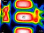
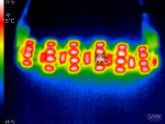
I let it run for a few minutes at 5A, ~4.5V on my bench power suppply, and it seemed to reach equilibrium around 90-95C peak. No other heatsinking or fan on this besides my ceiling fan at medium setting, and ambient around 25C. Peak junction temp is rated at 170C so well within spec.

Despite not matching all the parallel loads, there wasn't a ton of variation in temperatures. There was one diode that was consistently the hottest, but I think only maybe 5-10C max difference between temps across all of them.

I haven't used it to actually calibrate the 8A buck module yet, still putting together the rest of the rig.


peak diode temp.jpg

Somewhat interesting note: the auto peak temp on this camera appears significantly lower from further away, but both the pics were taken after peak temps were at 90C or so.
all_diode_thermal.jpg
 
Joined
Sep 12, 2007
Messages
9,399
Points
113
Well..... Maybe the diodes are rated at that, but I like to double the rating anyway,


Indeed it is both fascinating and perplexing to me that most members here can reconcile the insistence of driving a test load at <25% rating... while in the same breath condoning the operation of an actual laser diode at 200%, 300%, and beyond its rated current.


edWnwcd.gif


Every one is free to use whatever they believe will work best for them


Provided the benefits and risks are understood, yes. See? That wasn't so hard. I like this tune better than your previous:

For DC purposes, you'll need to use 4 times the current rating for the diode


Edit: Oh, and one more thing. Being called out for being wrong doesn't make you a victim of "abuse." Your stance on this is pretty f:)cking insulting to actual victims of abuse.
 
Last edited:
Joined
Sep 20, 2013
Messages
17,254
Points
113
I never claimed to be a victim here. I just said your abusive nature hasn't changed and that is something most members here can agree with. There are polite ways of trying to correct someone and then there is yours. I reiterate, these silicon rectifiers are the least expensive devices you will find in electronics and, at less than 10 cents each, why not use higher current diodes?
 
Last edited:
Joined
Jan 29, 2014
Messages
12,031
Points
113
Our diodes are often over driven, I agree, like a candle which burns very brightly.... you know the rest of it.
 
Joined
Jul 10, 2015
Messages
9,799
Points
113
Mj0vKzF.gif


Paul is making shit up again. Ignore him.

It very clearly states on the datasheet that 3A is the rating, under the condition "Maximum average forward rectified current 0.5" (12.5 mm) lead length at TL = 105 °C." And 3A DC is 3A average forward current by definition. You can go WAY above this for short durations. 200A for 8ms or 60A for over a second. Don't take my word for it. Just read the datasheet:

You too, Paul. Maybe you'll learn something. It's all there, black and white, clear as crystal. If you wanna over-engineer something as simple as a feggin test load, fine - you do you. But to insist to everyone that building a device short of your standards is unacceptable... is just asinine of you. Take your elitism elsewhere.

thehans, Since you'll be running these for maybe a minute at a time, 2 in parallel is fine. There may be a slight imbalance in the current sharing, but it really doesn't matter for these short durations.

Facts are fun.......this is how we learn. :D
Personally I think the correct information has the greatest value, I know that I want to give people who ask the correct information, so when someone doles out incorrect information and no one corrects it then I am at risk of repeating it and sounding like a fool, so in short I value correction by knowledgeable people much more than tap dancing around someone's ego who has given out poor/incorrect information and in truth a harsh correction gets the persons attention and deters them form spreading ignorance.
 
Joined
Jan 29, 2014
Messages
12,031
Points
113
I'm not sure if you misunderstood me Cyp, I meant I like to double the needed PIV and current ratings of silicon diodes, not laser diodes. Sometimes, if the physical size of the part isn't a problem, I will quadruple the needed ratings. Maybe overkill beyond the specified ratings for the usage, but I've never had a diode fail when I do, and I have when operating at the stated ratings of the device.

I've been annoyed from time to time when a member seems to only want to respond to posts to correct someone, otherwise never joining in on anything, but I also understand it is far too easy to judge someone from what you see posted, or just text, not really knowing the person. This can go both ways, we might accept someone we only know through posts but in person, you wouldn't, and vice versa, sometimes you find out they aren't the dirty dog you thought they were from what you have seen online.
 
Last edited:
Joined
Sep 20, 2013
Messages
17,254
Points
113
Look, my point was no one cares about the Vf of a rectifier when used as such, but when you use it as a load that is a totally different story. We used to buy those 3 amp silicon rectifiers back in the early 1970s in several thousand lots for a couple of cent a piece. I have changed many hundreds of them during the first half of the 1970s in television sets even though they were only pulling a little over 2 amps. As they heat up the Vf changes on them and so does your load. The 10 amp rectifiers are less than a dime a piece. When used in a dummy load for less than 2.5 amp drivers they hardly heat up at all. There's your knowledge, Robert.
 
Joined
Jan 29, 2014
Messages
12,031
Points
113
You are correct, but if I don't know all of the specs of a diode, I won't know if I want to use it or not. PIV isn't a big deal when used in DC circuits as there won't be inverse voltage. That said, for our laser diode pointers, we won't exceed forward voltage on the majority of the common rectifier diodes because we are already so low, but, we could exceed current handling capability. Regardless, for myself, I want to see all of the specs before I use one.


Top