Welcome to Laser Pointer Forums - discuss green laser pointers, blue laser pointers, and all types of lasers

LPF Donation via Stripe | LPF Donation - Other Methods

Links below open in new window

ArcticMyst Security by Avery

HELP! Hall Effect Switch Doesn't Turn On MOSFET...

Joined
Aug 25, 2012
Messages
116
Points
0
Good afternoon everyone!

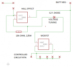
I am in a project right now in which I am building a circuit that uses a hall effect sensor (linear) to turn on a MOSFET. I've come across the below schematic, and have tried to wire it as shown. I have also tied the opposite side of the resistor to ground (negative battery terminal) still with no joy. I can get all the voltages I'm supposed to, just no forward driving on the MOSFET.

attachment.php


I suspect the 'FET might be the culprit, although I thought I had all the bases covered. It is a logic-level MOSFET with low enough current and voltage to be useful, and 2V should be plenty to forward-drive.

Anyways, the hard data for the components:

Diodes Incorporated AH49E (link)

NXP Semiconductor MOSFET, PMV45EN2 (link)

The schematic, as it is today:

attachment.php


Notes on Above:

The voltage tuning diode has been removed and shorted, so no need to worry about that. It is used to tune the sensitivity of the hall effect component, which will be useful once the circuit works!

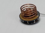
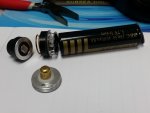
The upper left contact farm is power and mechanical switch contacts. It's all VCC, supplied by a single Li-Ion battery, 3.7-4.0 VDC.

"Controlled Circuit Return" would be the case connection.


BONUS: If you help me getting it working, I'll tell you what the circuit is for!!! It is not only laser related but also a component I'm hoping to incorporate in my final this semester.
 

Attachments

  • Hall Effect MOSFET Circuit, Example.gif
    Hall Effect MOSFET Circuit, Example.gif
    3.3 KB · Views: 1,249
  • Schematic, REV20.png
    Schematic, REV20.png
    7.7 KB · Views: 631
Last edited:


Benm

0
Joined
Aug 16, 2007
Messages
7,896
Points
113
What voltage are you measuring between gate and drain of the mosfet, directly on the component pins?

The mosfet requires 2.5 volts to properly conduct (well, over an amp with some drop), the output voltage of the hall sensor is it's supply voltage minus 1 volt, so that's pretty tight on 3.7 volts batteries.

You also have the 'voltage tuning' diode in there that will not do anything in this setup as there is no resistor to ground after it unless your mosfet gate leak current is substantial.
 
Joined
Aug 25, 2012
Messages
116
Points
0
What voltage are you measuring between gate and drain of the mosfet, directly on the component pins?

The mosfet requires 2.5 volts to properly conduct (well, over an amp with some drop), the output voltage of the hall sensor is it's supply voltage minus 1 volt, so that's pretty tight on 3.7 volts batteries.

You also have the 'voltage tuning' diode in there that will not do anything in this setup as there is no resistor to ground after it unless your mosfet gate leak current is substantial.

That was the key my man!!! Thanks a lot!!!

I must have been reading the gate-source voltage chart incorrectly, or it was something else I didn't understand. At first I got it going, and I thought that I shorted the leads together. But now, it is definitely working with nothing but a magnet and my finger, to keep the contacts aligned correctly.

So... to educate myself, how did you come up with 2.5 VDC? I'm sure MOSFETS and I are going to have a wonderful relationship together, but to make sure it wasn't a one-night-stand I'll have to know how to implement them properly!
 
Last edited:
Joined
Aug 25, 2012
Messages
116
Points
0
All right, all right... AS PROMISED I will make this thread a bit more interesting.

The final product is a magnetic interlock developed to add one more layer of security to ridiculously high-powered handheld devices. The idea is to use a magnet carrying pusher to press the button on the back of the laser to turn it on. To illustrate exactly where I am on the project -- I don't even have the magnet in mind purchased yet!

attachment.php

Early revision boards, PowerTap, MagLock, and Tailcap (switch) Interface boards.

The MagLock system is designed to isolate the battery itself, so that no functions are available without the magnet. This is especially useful in exhibitions, where one may have several battery-powered devices on display. It would be silly to make someone wait while you loaded batteries in each one, so why not have a cap/strap/socket to activate the laser, without taking it apart. This saves you from spilling components everywhere and saves someone else from habitually or accidentally turning your light saber on.

attachment.php

PowerTap board, showing the enlarged underside coontact area, allowing for the power wire for the circuit.

attachment.php

Two lower boards, before joining.

By using the battery for the interlock function, the MagLock system is also modular, so that devices that use swappable laser/flashlight heads won't have to worry about losing that capability.

While the hall effect sensor is rated for 8 volts, the MOSFET can handle up to 30 VDC. The circuit board was designed with double load-rated traces to support 4A continuous operation, 5A if below 5 seconds continuous. This allows the device to be compatible with a wide range of devices, from pointers to death rays.

attachment.php

Married boards, close up. Check out those springs I turned on my lathe/someone else's drill press.

attachment.php

The whole assembly. How about those ratings on the underside?

The one tricky part to making this work: You must isolate the rear click-switch. On this host it was accomplished by wrapping some electrical tape around the switch mount. The circuit can also be powered in situations where you have a midship switch. I have also tested this on my Aurora C6... It will fit with little modification. Also barely pictured are the plastic spacers that go around the contact springs for the rear switch. They were made by rubbing a hacksaw blade over ink pen parts.

There are several pads for interfacing, regardless of setup or need. I also forgot to photograph the battery (-) side... I make an electrical tape doughnut to go over the thru-holes. Those are tied to the case connection, and are no good when in contact with the battery!!!

attachment.php

Module complete. Battery can be slipped out at any time, for charging.

What's next? Magnetic Tuning. I still have to acquire the magnets, and ensure that they have the 'reach' to interface with the Hall sensor. This may mean that I need a new MOSFET, one that can activate at lower voltages. This may also mean that I need a new general purpose diode. These components are going to be used to make sure the interlock isn't tripped by the accidental refrigerator magnet from defeating it.

I'm also planning on using this on a school project, due here in a couple of months. Hopefully it works well enough to get that grade!!!
 

Attachments

  • 20160822_120459 (800x450).jpg
    20160822_120459 (800x450).jpg
    143.1 KB · Views: 408
  • 20160822_131602 (800x450).jpg
    20160822_131602 (800x450).jpg
    119.1 KB · Views: 407
  • 20160922_134005 (800x600).jpg
    20160922_134005 (800x600).jpg
    173.7 KB · Views: 398
  • 20160922_141210 (800x600).jpg
    20160922_141210 (800x600).jpg
    155.3 KB · Views: 385
  • 20160922_141309 (800x600).jpg
    20160922_141309 (800x600).jpg
    170.3 KB · Views: 434
  • 20160922_141642 (800x600).jpg
    20160922_141642 (800x600).jpg
    188.1 KB · Views: 396

Benm

0
Joined
Aug 16, 2007
Messages
7,896
Points
113
Glad you were able to solve it!

So... to educate myself, how did you come up with 2.5 VDC? I'm sure MOSFETS and I are going to have a wonderful relationship together, but to make sure it wasn't a one-night-stand I'll have to know how to implement them properly!

This actually is a mosfet with a very low required gate-source voltage. Logic-level usually means it will turn on 'full' at 3.3 or 5 volts.

To figure it out, look at the datasheet, page 7, figure 6. If you check on the horizontal axis, look for the actual voltage drop you can allow, perhaps 1 volt before below battery voltage to power the laser. If you look at the Vgs curve for 2.2 volts you see it's only a fraction of an amp, but the 2.5 volts curve is at 2 amps at that same point.

You might mistakenly use figure 7 next to it, but note 2 things about this: It is at 5 volts between drain and source, and the scale is logarithmic with the top at only 1 mA. This chart is there to tell you when it reliably turns -off-, which is at 1.7 volts gate-source typically (output drops under 1 mA).

The table on page 6 lists "gate-source threshold voltage" as 1.5 volts typ, 1.0 min and 2.0 max, but notice the operating conditions there: ID = 250 µA, so 1.5 volts will give you a current of only 0.25 mA at that point. Good enough to drive a logic pin perhaps, but no chance to power a laser diode.


Top