Welcome to Laser Pointer Forums - discuss green laser pointers, blue laser pointers, and all types of lasers

LPF Donation via Stripe | LPF Donation - Other Methods

Links below open in new window

ArcticMyst Security by Avery

Head scratcher - can I make this circuit from relays, diodes and switches only?

rhd

0
Joined
Dec 7, 2010
Messages
8,475
Points
0
I've been scratching my head on this one for a bit, and thought I would see if any of the bright minds on here had any ideas.

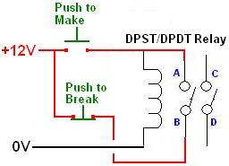
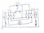
I want to design a circuit using a battery, a motor, 3 momentary switches and any number of relays and current rectifying diodes required.

- Pressing switch "trigger" turns on the motor, and it will continue running, even when trigger is released until a lever attached to monitor presses switch "endstop A", then the motor will stop. Pressing "trigger" again will now cause the motor to start moving in the other direction until it hits switch "endstop B". And so on.

This could be done in arduino, etc, but I want to use solely mechanical relays.

Possible?


diachi

0
Joined
Feb 22, 2008
Messages
9,700
Points
113
What you're looking for is some latching relays by the sound of things. I'd have to think about it more to come up with a circuit, but that's what you're looking for anyway I think.
 
Joined
Sep 12, 2007
Messages
9,399
Points
113
What kind of motor are you using? Is it AC or DC? For a DC motor, I think this would be easy with a push button, 2 NC limit switches, and 2 DPST relays. A latching relay isn't required. AC might be tricky.
 
Last edited:

diachi

0
Joined
Feb 22, 2008
Messages
9,700
Points
113
What kind of motor are you using? Is it AC or DC? For a DC motor, I think this would be easy with a push button, 2 NC limit switches, and 2 DPST relays. A latching relay isn't required. AC might be tricky.


A latching relay might be required depending on how he wants the momentary switches to work. I.e., single press, motor stays on. Or hold to keep motor on. I was assuming the former scenario.

Limit switches would be required to stop the motor either way.
 
Joined
Sep 12, 2007
Messages
9,399
Points
113
A latching relay might be required depending on how he wants the momentary switches to work. I.e., single press, motor stays on...

You clearly don't have much experience with relays. One (very common) method is to use the output of the relay contact to power the coil. That way, once the coil is energized by the push button, the coil remains on until the current is interrupted (with a limit switch in this case)

Example building block:

make-latching-relay-with-a-dpst-relay.jpg


I can draw something up in 20 minutes, but if I guess the motor wrong, I'd need to rewrite everything so I'm waiting on that response.
 
Last edited:

rhd

0
Joined
Dec 7, 2010
Messages
8,475
Points
0
It is a DC motor I'll be using.

I've been able to figure out how to make a setup where the two NC momentary buttons would serve as "stops" using Cyparagon's approach. Separately, I've been able to figure out how to make a circuit that reverses polarity when endstops are pressed. Where I've hit a roadblock, is figuring out how to combine the two, so that the endstops serve both functions with one button, ie, stopping the movement and also changing direction (or at least doing something such that the direction changes on next triggering of the circuit).
 
Joined
Sep 20, 2008
Messages
17,622
Points
113
It can be done with electro-mechanical parts but seems a
little convoluted when it would be so much easier with a
small 8pin Micro-controller for the logic.
Still needs a reversing Relay (or H-Bridge) and 2 end stops
and one Push Button.

Is there a reason why it must only be built with the parts
you outlined ??


Jerry
 
Last edited:

diachi

0
Joined
Feb 22, 2008
Messages
9,700
Points
113
You clearly don't have much experience with relays. One (very common) method is to use the output of the relay contact to power the coil. That way, once the coil is energized by the push button, the coil remains on until the current is interrupted (with a limit switch in this case)

Example building block:

make-latching-relay-with-a-dpst-relay.jpg


I can draw something up in 20 minutes, but if I guess the motor wrong, I'd need to rewrite everything so I'm waiting on that response.


Good point. You're right, I don't have much experience with relays.
 
Joined
Sep 20, 2008
Messages
17,622
Points
113
You clearly don't have much experience with relays. One (very common) method is to use the output of the relay contact to power the coil. That way, once the coil is energized by the push button, the coil remains on until the current is interrupted (with a limit switch in this case)

Example building block:

make-latching-relay-with-a-dpst-relay.jpg


I can draw something up in 20 minutes, but if I guess the motor wrong, I'd need to rewrite everything so I'm waiting on that response.
That is still a latching relay.
That would be an electrically latched relay.
as opposed to a mechanical latching relay
that diachi was probably thinking about.
Either way RHD would still require a type of
latching relay (or circuit) if he didn't want
to use a Micro Controller.

Jerry
 
Last edited:

diachi

0
Joined
Feb 22, 2008
Messages
9,700
Points
113
That is still a latching relay.
That would be an electrically latched relay.
as opposed to a mechanical latching relay
that diachi was probably thinking about.
Either way RHD would still require a type of
latching relay (or circuit) if he didn't want
to use a Micro Controller.

Jerry


Yep, technically the same thing, although should be easier to find a DPST relay than the latching relay with an RS pin that I was referring to. Either locally or by salvage.
 
Joined
Sep 20, 2008
Messages
17,622
Points
113
Yeah easier to find and a lot less expensive than a
mechanically latched relay.
I have an old one in the shop somewhere that has
2 coils for latching one way or the other.


Jerry
 
Last edited:
Joined
Sep 12, 2007
Messages
9,399
Points
113
That is still a latching relay.

That is a regular relay in a latching circuit. Diachi (I believe) was referring to a relay that requires no holding current. A relay that requires no holding current is NOT required here... it might even make it harder. If you buy a "latching relay", you will not get the circuit I posted, you will get a different device entirely.

This is taking too long in mspaint. I'll going to wait until I get home in a few hours to upload a sketch photo instead, but I do have a solution. First draft anyway. I had to make them 3PST ($2 shipped on ebay) and add 2 diodes. (4 total if you count flyback diodes)
 
Last edited:
Joined
Sep 12, 2007
Messages
9,399
Points
113
Good god, no one wants to wire up 47 relays to turn a motor, Sean. That's when you give up and switch to arduino.

Here's what I came up with. It's basically a low-tech H-bridge to switch polarity. One obvious weakness is that it shorts 12V if you press the power button while one of the limit switches is not engaged. A DC breaker would remedy that, though. I'm sure it could be improved, but like I said, first draft.

attachment.php
 

Attachments

  • relay_draft.png
    relay_draft.png
    83.6 KB · Views: 297
Joined
Mar 25, 2016
Messages
475
Points
0
I think it would be kind of neat to see a 50+ relay circuit in action. Would look and sound cool too :p yes I agree with you its not at all practical, but I don't think thats the OP's point, he said
and any number of relays and current rectifying diodes required.
and
This could be done in arduino, etc, but I want to use solely mechanical relays.


Top