Welcome to Laser Pointer Forums - discuss green laser pointers, blue laser pointers, and all types of lasers

Buy Site Supporter Role (remove some ads) | LPF Donations

Links below open in new window

FrozenGate by Avery

Fried diode... why?

Joined
Mar 25, 2013
Messages
88
Points
0
So I have a question,

I was working on a simple build using a 300mW red diode and a driver with current set at 400mA. Before i put the laser together and soldered my final connections, I tested the setup and the diode worked fine. So I unhooked what I needed to, and then soldered my final connections and assembled the laser. After everything was completed I powered the laser on and dot a bright beam for a split second and the diode died (LED'd the diode). My question is how did I fry this diode, and how can i prevent it in the future. Is it from not properly discharging the capacitor before connection ? I thought I did, but if that is the case can someone give me a quick run-down on how to properly discharge it?

Thanks


Discharging a driver is very easy. Hold the two leads to the diode for a brief moment.
Can you tell us what driver you use ?
 
I am using a selectable 1.8A Xdrive V6... It's set just under 400mA.
 
The X-driver is a buck driver. The input minus and the output minus are not continuous. They must not have a connection between the both minuses.
The red diode is case negative and made an electrical contact with the battery minus.
Your diode is shorted and that is why it has fried.
 
So how would I make it non continuous ? Is the goal to make sure the circut is never totally completed ?
 
My normal setup is batt+ > driver+ > diode+ > diode- > driver- > make connection with host via wire in between pcb
 
Use a linear driver or a Flexdrive. They have continuous negative.
Or use a case neutral diode with the buck driver.

A case negative diode and the buck is not a good combo. You must isolate the diode module from the rest of the host.
 
Basically the idea is to have the driver that has both the negative input and negative output at the same point.

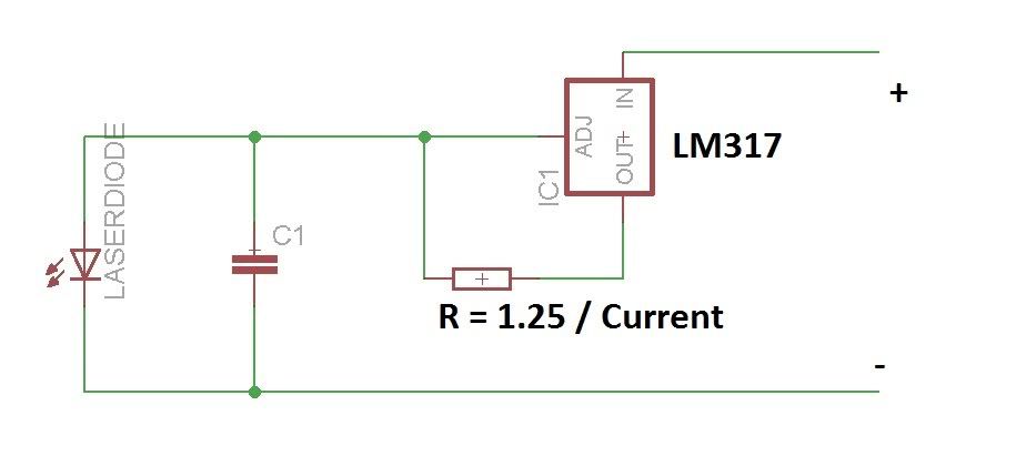
For example if you look at the schematic of an LM317 based linear step down driver here:


You can see that the negative input and negative output do not have any components between them, which is to say: it's "continuous negative".

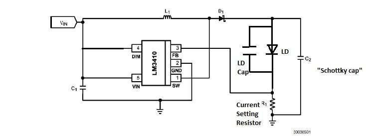
You will see that boost drivers such as this one:


...have components interrupting that. That means it's not the same voltage point - but you were ignoring that, and by having the diode's case (negative input) connected to hosts' case, you were connecting it to both the driver's negative input AND output, therefore bypassing the driver partially and causing damage to it.
 
This thread has me confused... I bought this driver Mohgasm Linear Driver - $6.99 : Mohgasm LLC, Have you experienced one lately? I'm new to this and I don't want to make the same mistake, Can someone explain to me how this would be wired... I thought I would just wire d+ d- to the diode and then vin to the battery + and gnd to the case, is this not what i should do? should I bypass the case and wire the gnd to the - on the battery?
 
Connecting the diode - and the battery - depends on the driver :

linear driver = diode - and the battery - are the same. You can connect it.
boost/buck driver = diode - and the battery - are NOT the same.

There are special drivers like the Flexdrive that is a buck/boost AND have the same minus.
 
Is this the correct wiring? I see some people bypassing gnd and instead wiring the battery - right to the diode, with the case pin going to the driver gnd.. i dont understand.
XIEpbn1.png
 
That is the correct wiring. I recommend you don't bypass unless you know why, search the forum for "continuous ground"


Back
Top