Welcome to Laser Pointer Forums - discuss green laser pointers, blue laser pointers, and all types of lasers

LPF Donation via Stripe | LPF Donation - Other Methods

Links below open in new window

ArcticMyst Security by Avery

Flashlight optics and reflectors.

Joined
Nov 6, 2014
Messages
94
Points
0
OK. I'll likely be taking your advice. This is what I'm currently planning on purchasing. However, I'm not entirely sure about the FET driver and if that's what I want to use. It sounds like it uses direct battery voltage and uses PWM to control the brightness settings? If so, wouldn't the LED be damaged on a 100% PWM as that's essentially just hooking up a LED straight to a battery? I'm just trying to wrap my brain around that as the only drivers that I'm somewhat familiar with are all current limited boost or buck converters.

Also, what is a turbo timer? It's also something I'm unfamiliar with. Appologies if that's a noobish question.


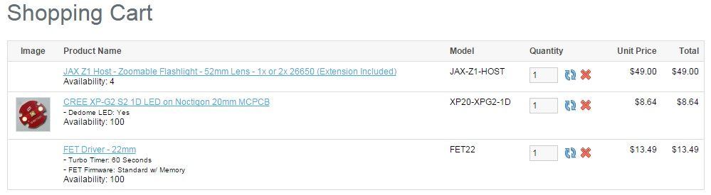
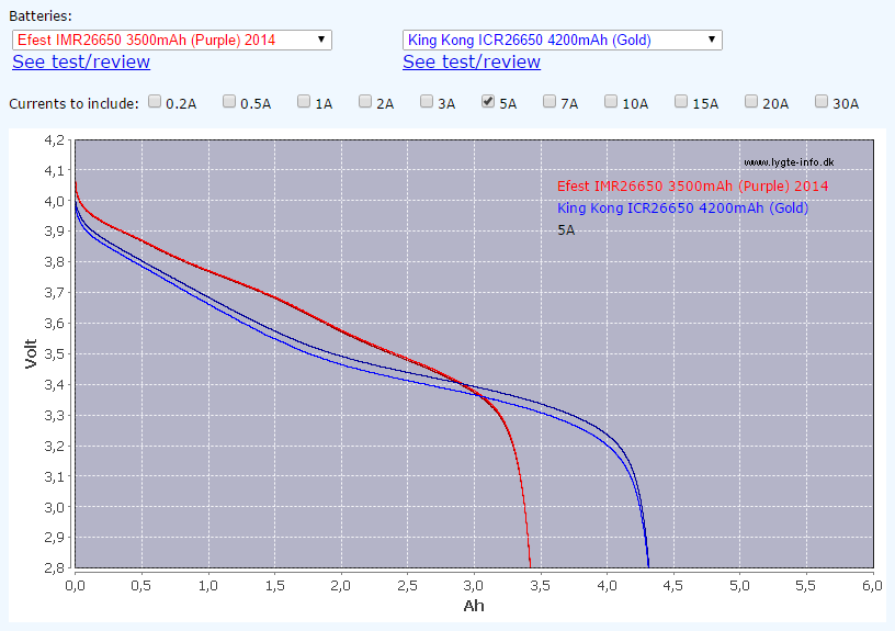
I think that's everything I'll need for a throwy flashlight, but am I missing any parts that might not be obvious to me? I know I'm missing a battery, I've yet to see if an 18mm*130mm battery exists or if I can explore the possibility of getting a battery spacer to utilize the extension tube. (I kind of like the tube)

Also, thanks to will manners for all the interesting reading material you posted earlier. I have a much better understanding of things after exploring those pages last night and most of today.
 
Last edited:


Joined
May 12, 2013
Messages
751
Points
43
I'm not entirely sure about the FET driver... ...It sounds like it uses direct battery voltage and uses PWM to control the brightness settings? If so, wouldn't the LED be damaged on a 100% PWM as that's essentially just hooking up a LED straight to a battery?

That's exactly what it does.

That's why it's essential for the LED to be on a DTP (Direct Thermal Path) copper MCPCB. An XP-G2 will not gain in output above ~2.2 amps on a normal Aluminium MCPCB with a dielectric layer underneath the LED. However, an XP-G2 will increase in output right up until around 4.5 amps (see here for some output graphs on the XP-G2 - Emitter Test Results: XML2, XP-E2, XP-G2, Nichia 219

Because of the direct drive nature of the circuit you DO NOT want to use 2 Li-ion's with the extension tube, that will instantly kill the LED.

Unlike Laser diodes, LED's are much more durable and can take being overdriven to almost 3X their rated current. The only difference between the FET driver and direct drive is that it allows user configurable modes, low voltage protection, reverse polarity protection and turbo timer whilst having direct drive characteristics on 100%.

Also, what is a turbo timer? It's also something I'm unfamiliar with.

The turbo timer steps down the current to the next highest PWM level (50% for example) to prevent overheating. Personally I don't like the turbo timer since I would rather make my own judgement as to when it's about to overheat. Although it is useful if the light is accidentally left on unattended.
 
Last edited:
Joined
Nov 6, 2014
Messages
94
Points
0
I thought that LEDs that are run directly to a battery would be susceptible to thermal runaway because there wouldn't be any current regulation. What regulates the current here besides the internal resistance of the battery? Or does it not matter with this kind of FET driver if you use the correct battery voltage?

Going by this chart a 130mm battery must not exist. :(
List of battery sizes - Wikipedia, the free encyclopedia

What kind of driver options would there be for a light like this if I wanted to run two batteries with a buck converter? Perhaps there is a particular reason a FET driver was suggested.

I noticed that on mountain electronics website that they had many slightly different kinds of CREE XP-G2. What's the difference between them?:undecided:
 
Last edited:
Joined
Nov 6, 2014
Messages
94
Points
0
I'm slowly starting to figure this stuff out.

I found a CREE data sheet about binning and labeling of their LEDs. So, if I understood all of this correctly a Cree XP-G2 S2 1D has the following characteristics:

S2 = refers to the performance group. S2 is second only to the S3 performance group. S2 refers to a 148 min and 156 max lumen ouput in lumens at 350ma.

1D = refers to the color temperature and chromaticity of the LED. So in this case it's somewhat blueish. However, I read that dedoming causes the color to shift to a warmer color temperature so it might look more white than blue after dedoming.

Hopefully, the above info I found is correct.

I searched around a little for a XP-G2 S3 with a cool color temperature. I didn't find anything. How does one go about finding whether this has ever existed?

Also, is there any reason this battery wouldn't work?
http://www.mtnelectronics.com/index.php?route=product/product&product_id=414&search=efest+26650

The green Efest has a lower maximum amp rating, but more mAh. This should mean more run time compared to this, right?
http://www.mtnelectronics.com/index.php?route=product/product&product_id=354&search=efest+26650

I don't know if these flashlight batteries are anything like radio control lithium batteries where the battery amp ratings should be taken with a rather large grain of salt as they're usually greatly exaggerated.
 
Last edited:
Joined
May 12, 2013
Messages
751
Points
43
I thought that LEDs that are run directly to a battery would be susceptible to thermal runaway because there wouldn't be any current regulation. What regulates the current here besides the internal resistance of the battery? Or does it not matter with this kind of FET driver if you use the correct battery voltage?

Thermal runaway does not apply in this situation, since the LED can only draw as much current as the cell can provide. Which in this case is limited by the vf (operating voltage) of the LED. Further to this, the cell will have significant voltage sag, especially under high currents, which in turn will limit the amount of current supplied to the LED. Current regulation is only required in situations where the power source has a significantly higher (or lower) voltage than the operating voltage of the LED/LD. Even laser diodes can handle direct drive as long as the applied potential difference (voltage) is above the vf of the lasing threshold but not significantly above its rated operating voltage.

What kind of driver options would there be for a light like this if I wanted to run two batteries with a buck converter?

Not many...

For a 2S cell configuration to be able to work with an XP-G2 the buck driver must be highly efficient in order to handle the extra overhead voltage. And there aren't many drivers that can do that whilst having modes and low voltage protection. I suggested the 22mm FET driver because it has been very extensively tested and developed, plus there are not many other 22mm drivers.

I'm slowly starting to figure this stuff out... ...Hopefully, the above info I found is correct.

Yep, that's all correct :) If you haven't seen the ANSI white colour spectrum illustration before it should explain a lot.

ANSI White color spectrum. Changed the pic to a link, since it seemed obtrusively large...

I searched around a little for a XP-G2 S3 with a cool color temperature. I didn't find anything. How does one go about finding whether this has ever existed?.

XP-G2 S3 LED's do exist although not in higher colour temperatures (at least not at the moment). MTnelectronics sells an XP-G2 S3 3C LED, although it would prove unsuitable for dedoming since the tint would be dramatically warmer in colour temperature.

Also, is there any reason this battery wouldn't work?
Efest Green 4200mAh 26650 Battery

The green Efest has a lower maximum amp rating, but more mAh. This should mean more run time compared to this, right?
Efest 26650 3500mAh Hi Discharge 26650 Battery

Correct, the green Efest cell will work fine in this setup. It just means that the LED will have a lower maximum output but will have better runtime. When choosing between different cells it is usually a matter of compromise between the user desiring a higher max output or a longer overall runtime.

The runtime graph below compares the discharge capacity @ 5 amps between the Efest purple 3500mAh IMR cell against the KK ICR 4200mAh cell (similar to the Efest green cell). As the graph indicates, the 4200mAh cell has a higher overall capacity, but has much higher voltage sag under load. For single cell configurations, we are more interested in the discharge capacity down to 3.6 volts. Which means that the Efest purple cell will have longer runtimes down to 3.6 volt @ 5 amp compared to most higher capacity cells.

Comparator

dqwsqwdxdcxqadasd_zpsf7f0015f.png


I don't know if these flashlight batteries are anything like radio control lithium batteries where the battery amp ratings should be taken with a rather large grain of salt as they're usually greatly exaggerated.

The amp ratings given to batteries from brand name companies such as Panasonic, Sanyo, Samsung etc are not exaggerated, they are simply the max rated discharges that the cell can safely handle under ideal conditions. Amp ratings from manufacturers who simply re-wrap cells such as Efest, Keeppower, AW etc, tend to state very optimistic amp ratings which usually do not hold true to the original ratings given to the cell by brand name companies.
 
Last edited:
Joined
Nov 6, 2014
Messages
94
Points
0
Thermal runaway does not apply in this situation, since the LED can only draw as much current as the cell can provide. Which in this case is limited by the vf (operating voltage) of the LED. Further to this, the cell will have significant voltage sag, especially under high currents, which in turn will limit the amount of current supplied to the LED. Current regulation is only required in situations where the power source has a significantly higher (or lower) voltage than the operating voltage of the LED/LD. Even laser diodes can handle direct drive as long as the applied potential difference (voltage) is above the vf of the lasing threshold but not significantly above its rated operating voltage.


Not many...

For a 2S cell configuration to be able to work with an XP-G2 the buck driver must be highly efficient in order to handle the extra overhead voltage. And there aren't many drivers that can do that whilst having modes and low voltage protection. I suggested the 22mm FET driver because it has been very extensively tested and developed, plus there are not many 22mm drivers.


Yep, that's all correct :) If you haven't seen the ANSI white colour spectrum illustration before it should explain a lot.

PFIYj3O.jpg


XP-G2 S3 LED's do exist although not in higher colour temperatures (at least not at the moment). MTnelectronics sells an XP-G2 S3 3C LED, although it would prove unsuitable for dedoming since the tint would be dramatically warmer in colour temperature.


Correct, the green Efest cell will work fine in this setup. It just means that the LED will have a lower maximum output but will have better runtime. When choosing between different cells it is usually a matter of compromise between the user desiring a higher max output or a longer overall runtime.

The runtime graph below compares the discharge capacity @ 5 amps between the Efest purple 3500mAh IMR cell against the KK ICR 4200mAh cell (similar to the Efest green cell). As the graph indicates, the 4200mAh cell has a higher overall capacity, but has much higher voltage sag under load. For single cell configurations, we are more interested in the discharge capacity down to 3.6 volts. Which means that the Efest purple cell will have longer runtimes down to 3.6 volt @ 5 amp compared to most higher capacity cells.

Comparator

dqwsqwdxdcxqadasd_zpsf7f0015f.png


The amp ratings given to batteries from brand name companies such as Panasonic, Sanyo, Samsung etc are not exaggerated, they are simply the max rated discharges that the cell can safely handle under ideal conditions. Amp ratings from manufacturers who simply re-wrap cells such as Efest, Keeppower, AW etc, tend to state very optimistic amp ratings which usually do not hold true to the original ratings given to the cell by brand name companies.

Thanks for being so helpful and understanding of my noob questions. I've placed an order with mountain electronics for the LED, Driver,battery and Jax Z1 host.

I'm still going to look for a decent charger for a 26650 battery. Perhaps I can find a tray and just charge them with my RC hobby li-ion charger.
 
Joined
Nov 6, 2014
Messages
94
Points
0
OK, another noob question.

Should I be using thermal compound or thermal adhesive? I assume that I need to be using adhesive to mount the LED to the pill.

Also, is there a huge difference between Arctic Silver Premium or Arctic Alumina for the purposes of an LED?

I've also heard of something called reflow soldering. Is this also an option? If it is I can't seem to find somewhere that has paste for reflow soldering.

Also, is it really as easy as it looks?

 
Last edited:
Joined
May 12, 2013
Messages
751
Points
43
Should I be using thermal compound or thermal adhesive? I assume that I need to be using adhesive to mount the LED to the pill.

Definitely use thermal compound. If for whatever reason you want to remove the MCPCB you're not gonna get very far with it glued in there...

Also, is there a huge difference between Arctic Silver Premium or Arctic Alumina for the purposes of an LED?

If you are referring to Arctic Alumina thermal compound then I have no clue what the differences are.

I've also heard of something called reflow soldering. Is this also an option? If it is I can't seem to find somewhere that has paste for reflow soldering.

Mechanics Solder Paste - 63/37 - 36g

It is an option; many individuals believe re-flowing the MCPCB directly to the pill offers superior thermal characteristics, although I am not sure if there is solid evidence to support this theory.

Also, is it really as easy as it looks?

Yes it is. If you don’t have a butane torch you can use a stove top.
 
Last edited:
Joined
Nov 6, 2014
Messages
94
Points
0
Thanks, for the quick reply. I've heard that thermal compound is more a thermal grease than anything. Is thermal compound by itself enough to hold the LED in place? Just how tacky is the compound? I'm more worried about it coming lose through vibration or dropping the flashlight. I'm not familar with any of thermal paste, adhesive, or reflow soldering. Perhaps any my worries of the LED falling off if I use thermal compund are completely unnecessary.

If you think that thermal compound is sufficient, I may just get that as it's cheaper and more readily available than solder paste or thermal adhesive.
 
Last edited:
Joined
May 25, 2013
Messages
534
Points
28
I use thermal adhesive myself, but my plans are to never touch the LED again, i have removed Copper boards from pills that have used adhesive between them with pliers and twisting motion when thinks go wrong and it can be a bit of a hassle sometimes, but i guess if you use compound you might want to screw the board to the pill or something that keeps it in one place,
Is your Pill brass or aluminium, i think brass and copper are easy to reflow together but aluminium and copper may be a little bit more difficult BUT im not sure!
 
Last edited:
Joined
Nov 6, 2014
Messages
94
Points
0
I use thermal adhesive myself, but my plans are to never touch the LED again, i have removed Copper boards from pills that have used adhesive between them with pliers and twisting motion when thinks go wrong and it can be a bit of a hassle sometimes, but i guess if you use compound you might want to screw the board to the pill or something that keeps it in one place,
Is your Pill brass or aluminium, i think brass and copper are easy to reflow together but aluminium and copper may be a little bit more difficult BUT im not sure!

My Jax Z1 host should hopefully be arriving sometime today. I'll have to see what the pill looks like and see how well the LED fits in place. Perhaps if it's a snug enough fit, friction might help hold it along with the thermal compound. I'm still debating on what method to use for LED mounting. I already have some Arctic thermal compound purchased for another project that I've yet to complete. Hopefully, I'll have a better idea when I actually get my hands on the parts and pieces later today.
 
Joined
Nov 6, 2014
Messages
94
Points
0
I got most of my parts in today. I dropped the LED into the pill for a test fit and it seems that it's sort of a loose fitment. The LED seems to have a little side to side wiggle room. I may just see how it goes with the Arctic Ceramique 2 that I have on hand. Hopefully it's tacky enough that the LED will stay in place after the wires and retainer ring go on-top. I guess it's not the end of the world if I find out later that I need adhesive instead.

Also, do some drivers not require them to be soldered to the pill? This is a picture of a driver that is identical to mine from the internet:

2014-11-101700_zps6b1682c2.jpg


It has a contact that runs around the outer edge of both sides.

2014-11-11101749_zps52099aad.jpg


Here it is installed into a JaX pill with the driver retaining ring. I can't imagine there is room for solder between the retaining ring and the driver board? Hopefully, I'm correct that I probably won't need solder here?

Also, how critical is the centering of the driver on the pill? If it is super critical to have it centered to within 1/4 of a millimeter how does one go about doing such a thing? The only thing I can think of is adding a very thin strip of tape to the edges of the LED and using that to fill the very slight gap between LED and the pill.

Sorry guys. I ask way too many questions. :eek:

I'm going to try and document this build as I go. So far I need to find some time to take some pictures for you guys. I do know how you guys like your pictures.
 

3Pig

0
Joined
Oct 26, 2013
Messages
242
Points
0
I wouldn't recommend using thermal PASTE in a build like this, unless you can screw the LED to the pill, you'll want some thermal adhesive, and remember with thermal paste/adhesive less is more, thinner layer = better heat transfer

Don't think you need to solder the driver to the pill since its got that retaining ring, could be wrong though, driver centering isn't too important (If it fits its good), LED centering is kinda important, I center my LED's by eye and had no problems, you can adjust the LED centering while the glue is still setting.

Hopefully that helped somewhat, good luck with the build :D 
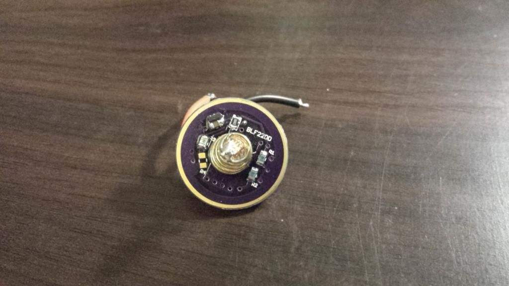
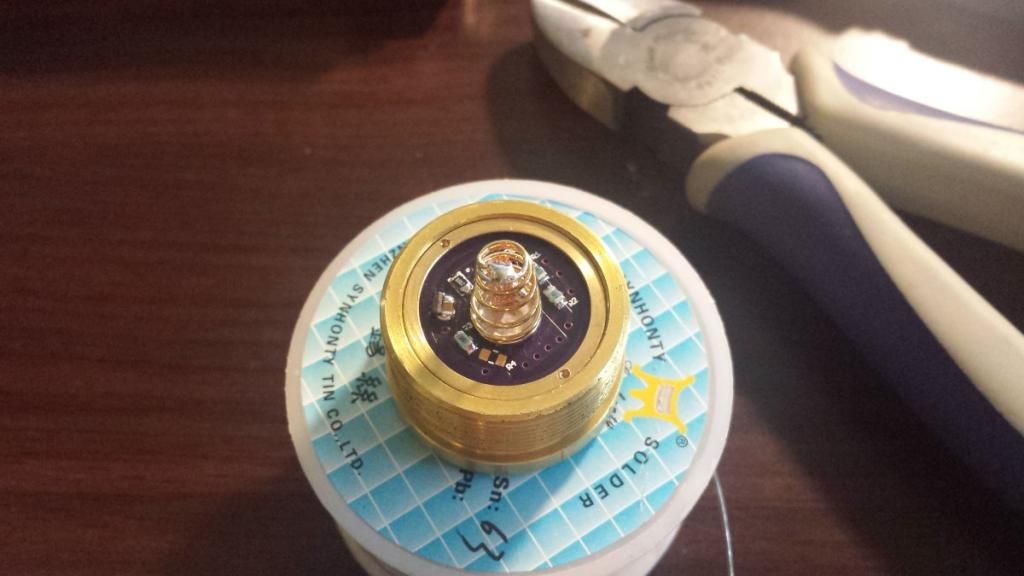
Going to be a monster thrower :drool:


Top