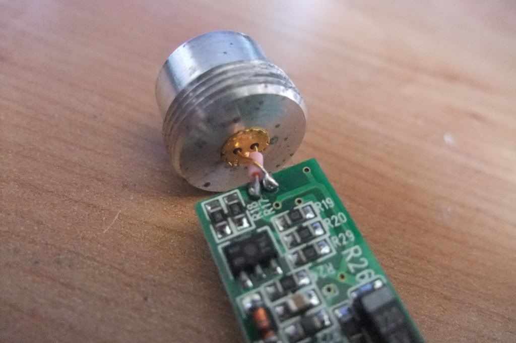
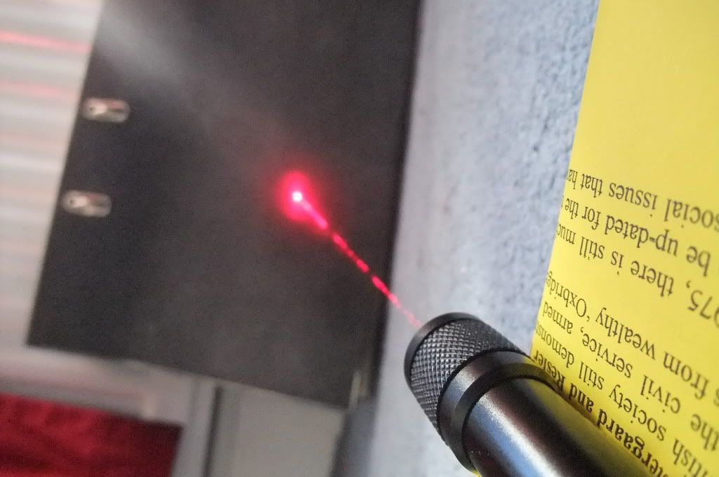
Your diode, although electrically connected correctly, is not
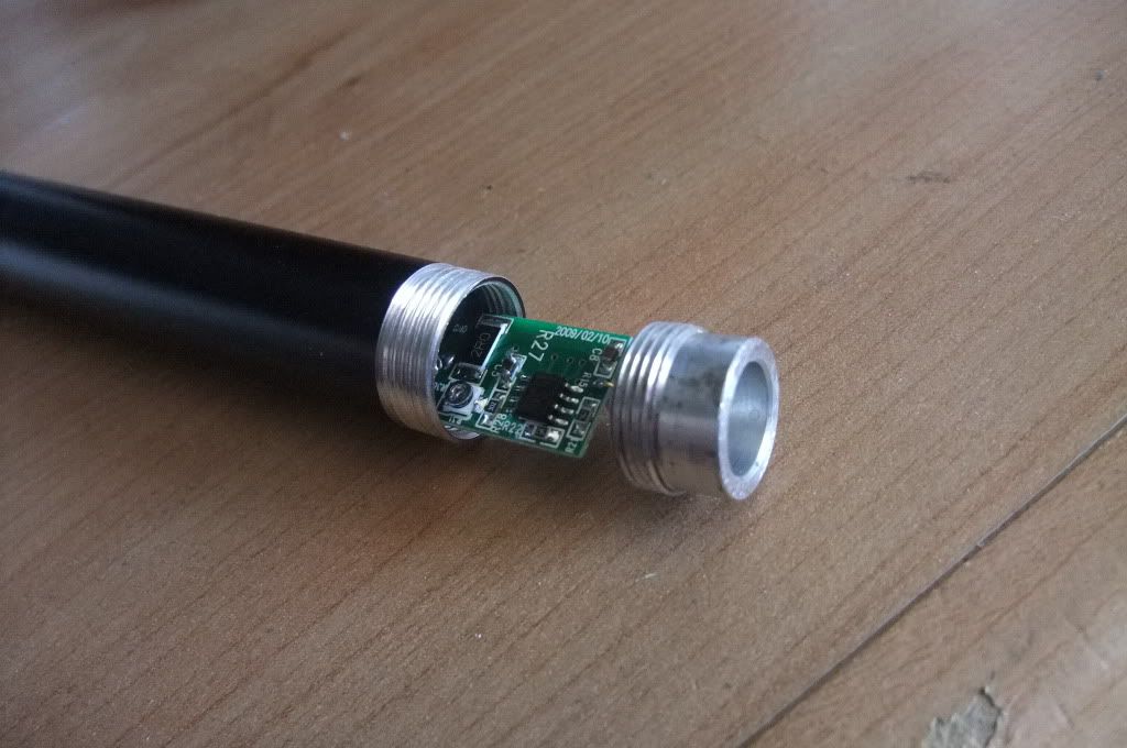
installed correctly. In your photo, the pin on the left of the diode, (you have it crossing over the +ve pin), should be connected to the pad on the underside. This would allow the pin soldered to the underside to be soldered to the top of the board and untwist all the pins. You will find that you will stress the pins and the joints in this configuration as the battery presses the board towards the diode. There should be no gap between the drvier board and the heatsink/diode. All should butt up and be flush allowing no movement.
The negative pin and the case pin have electrical continuity so the -ve pad and the single pad on the other side of the board are electrically connected.
If it works and is mechanically sound then you may want to leave it but for next time, the diode will install withoput having to bend or twist any pins. You might have to shorten them but they should remain straight.
If you have a DMM then remove the tail cap; touch one probe to the threads of the body that the tail cap screws into to and one to the end of the battery whilst reading Amps on your meter, (you may have to use the 5A or 10A setting, depending on your DMM). This will give you a good idea of what your driver is outputting. Subtract 20-30mA from the reading, (the power used by the driver), and the answer is what your driver is actually feeding the diode. Check back to the specs of your diode to see how much you can safely give it.
Well done on getting photons though!

M


