Welcome to Laser Pointer Forums - discuss green laser pointers, blue laser pointers, and all types of lasers

LPF Donation via Stripe | LPF Donation - Other Methods

Links below open in new window

ArcticMyst Security by Avery

first portable laser build! :)


Joined
Jul 22, 2010
Messages
54
Points
0
guys do you think i can just solder the bits together and itll work or should i adjust the pot?

it says its preset to 200ma, it says the laser shouuld run between 90(hot) and 140(cool) at 200ma on the laser diode page

should i put it down a little or leave it?

thanks :)
 
Joined
May 15, 2010
Messages
1,307
Points
48
it all depends on what the voltage is, it will run at 300mA at 6V at the highest setting
I'm running mine at around 225mA and burns realy well so i'd turn it down a little
 
Last edited:
Joined
May 15, 2010
Messages
1,307
Points
48
I'm not familiar with that driver, have you got a dummy load and DMM?? if so wind it up all the way and test the output then back off 1-2 turns untill you get the desired output

but take the power off each time you turn the pot also when you come to solder the diode on, short the +ve and -ve power terminals on the driver as the capasitor will be charged and will blow the diode
 
Joined
Jul 22, 2010
Messages
54
Points
0
ive got it all put together now and i done have a dummy load or dmm(dont even know what it is ;) ), ill upload some pics in a bit:)

i fiddled witht eh pot and i dont know what its set to so ill need to get a multimeter to measure the output so i can adjust it properly :p
 
Joined
May 15, 2010
Messages
1,307
Points
48
ok, DONT power the driver without either a dummy load (use the seach tab for that) or a diode or you will damage your driver !!! A dummy load basically acts as a dummy diode so you dont blow your precious diode :) good luck

*Edit* a DMM is a Digital Multi Meter
 
Joined
Jul 22, 2010
Messages
54
Points
0
yeah i didnt power it without the diode :p

and im gunner get a dmm soon so i can measure what the pots set at :)
 
Joined
Jul 22, 2010
Messages
54
Points
0
got my pictures:)
sorry they took so long:


DSCF1787.jpg


DSCF1789.jpg


got abit confused about why the pins were backwards?
DSCF1792.jpg


DSCF1795.jpg


deoderant in full daylight:
DSCF1799.jpg


deoderant in dark!!
DSCF1801.jpg


DSCF1802.jpg


i also just made a tiny laser keyring out of a couple of cheap crappy parts but they work ;)
ill upload a picture later on...


also i messed about with the pot earlier and ive got it set so if you turn it up a little the laser is very dim and any more and it wont turn on
 

Morgan

0
Joined
Feb 5, 2009
Messages
2,174
Points
0
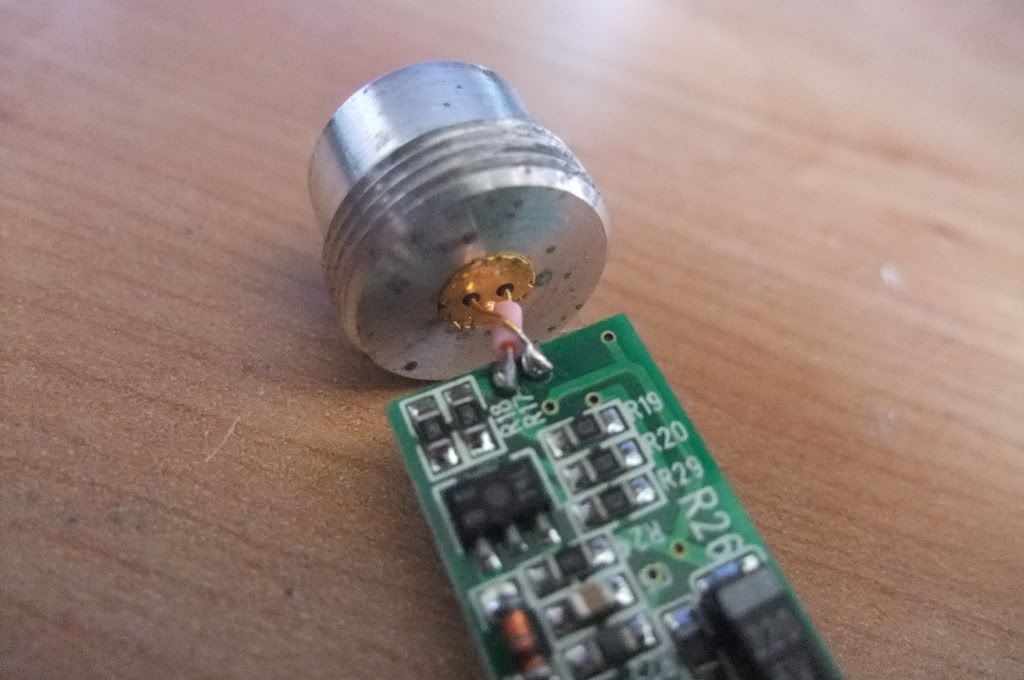
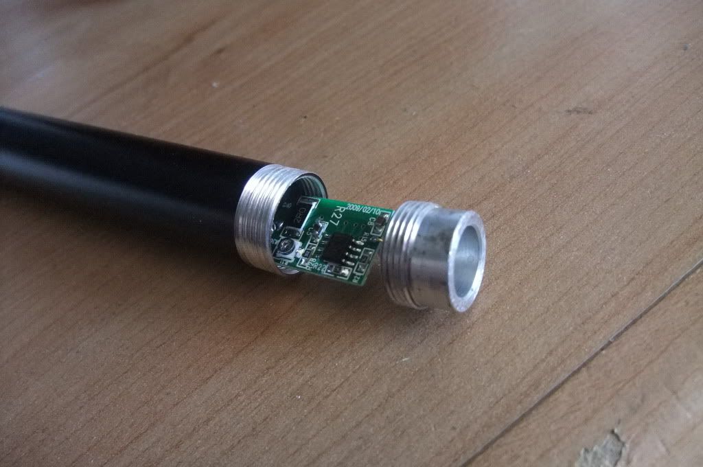
Your diode, although electrically connected correctly, is not installed correctly. In your photo, the pin on the left of the diode, (you have it crossing over the +ve pin), should be connected to the pad on the underside. This would allow the pin soldered to the underside to be soldered to the top of the board and untwist all the pins. You will find that you will stress the pins and the joints in this configuration as the battery presses the board towards the diode. There should be no gap between the drvier board and the heatsink/diode. All should butt up and be flush allowing no movement.

The negative pin and the case pin have electrical continuity so the -ve pad and the single pad on the other side of the board are electrically connected.

If it works and is mechanically sound then you may want to leave it but for next time, the diode will install withoput having to bend or twist any pins. You might have to shorten them but they should remain straight.

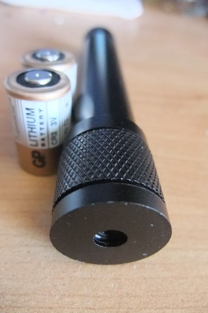
If you have a DMM then remove the tail cap; touch one probe to the threads of the body that the tail cap screws into to and one to the end of the battery whilst reading Amps on your meter, (you may have to use the 5A or 10A setting, depending on your DMM). This will give you a good idea of what your driver is outputting. Subtract 20-30mA from the reading, (the power used by the driver), and the answer is what your driver is actually feeding the diode. Check back to the specs of your diode to see how much you can safely give it.

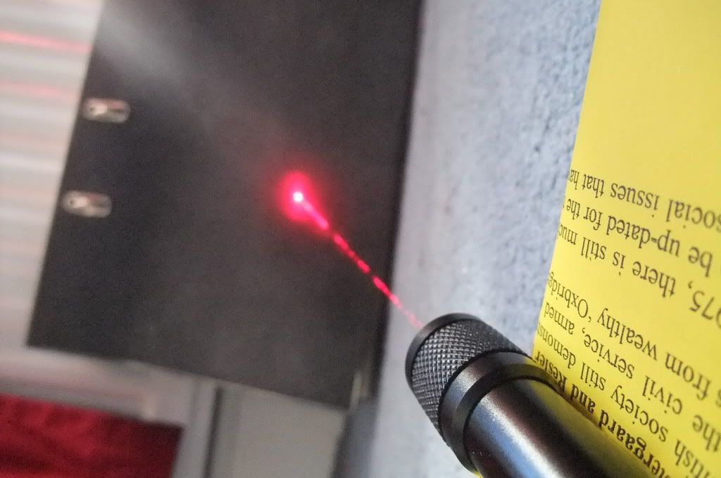
Well done on getting photons though! ;)

M
:)
 
Joined
Jul 22, 2010
Messages
54
Points
0
thanks for the explanation :) i was thinking of weather i installed it right earlier today :p

i think ill leave it the way it is until i either upgrade or make a new one as it weems to be working fine now :) none of the pins short each other out cause ive got the insulator on one of the crossing ones so im happy with leaving it:)

ill have to get myself a dmm so i can measure the amps:)

thanks again
matt
 
Joined
Aug 6, 2010
Messages
382
Points
0
Congrats Matt.
You will need a DMM for current testing. Only way to get the most from your build or even with your junk part ones, you can get a current set for long diode life.


Top