Welcome to Laser Pointer Forums - discuss green laser pointers, blue laser pointers, and all types of lasers

Buy Site Supporter Role (remove some ads) | LPF Donations

Links below open in new window

FrozenGate by Avery

First laser build

Joined
Oct 27, 2008
Messages
726
Points
0
hey i am new to these forums but i saw a couple videos on youtube (including the kipkay one...i know not to do that one after searching these forums) and they fascinated me so i decided to build my own laser.  I saw styropyro's laser tutorial and decided to build it (cause it looked easy and im new to this)  So i got the parts: a pre-installed sony diode in an aixiz housing from stonetek, AA holder, switch, and pot.   i have a couple of questions though
1) I got a 1k ohm pot.  In the video he used a 100 ohm pot.  Does it matter?
2) His camera isnt very good...so i couldnt tell where he soldered things...can anyone clarify?          
3) how do i know if my pot is at its maximum resistance
4) if this will make me fail miserably tell me now...lol  (<-- that isnt a question... )

Thanks in advance!


1) You will find it hard to set with a 1K pot as it is only the last little bit of the movement of the adjuster that is in the 100 ohm range (see drawing below).

2) Depends on driver you use

3)To find out if your pot is at the max resistance wind the adjuster to one end then use a multimeter set on ohms between the centre pin (wiper) and each of the outer pins ( resistance track) in turn, one side will read zero the other full resistance.

4) If you read the tutorials and understand what you are reading there is no reason to fail.

Regards rog8811
 

Attachments

  • 1K_to_100R.jpg
    1K_to_100R.jpg
    36 KB · Views: 134
Thankyou for your reply
   I have looked around the forums somemore and found that the rckstar driver works pretty well and the dorcy jr works well as a host and a driver...which do u think works better? Or if the circuit I talked about worked could you add a picture of where I solder things?
Thanks again
 
i kept searching...(bear with me here...) and found a video on how to make a Driver.  ( i am pretty sure it is DDL driver..) found here -->(i need 10 posts before i can post it but it is on metacafe...)  But i am still unclear on where to attach my diode and my power source.  If anyone can clarify it would be greatly appreciated.  thanks!
 
i bought all the components at radio shack but i got a 10uf capacitor...they didnt have any of the other kind... :'( would it still work? also i got a battery holder that holds 4 double a's (6 volts) would that be suitable for this circuit?

thanks for all your help!
 
also I got a 25 ohm pot in the video instead of the 100 ohm pot like it says in the diagram but it is also adjustable..will it work? Thanks
 
but i got a 10uf capacitor
That is the correct value, mfd on my drawing is just the way I was taught to do write it when I was a draftsman. ;)

also i got a battery holder that holds 4 double a's (6 volts) would that be suitable for this circuit?

With 6v it will not be long before the battery power sags and the regulator will drop out of regulation.
7.2v is the minimum.

I got a 25 ohm pot in the video instead of the 100 ohm pot

That will work fine, the driver will just have a higher minimum output current.

Regards rog8811
 
Its much more reliable (in my opinion) to just use resisters because you don't have to mess around with multi meters because some of my multi meters have internal resistance and will give you a false reading.

Simply take 1.25 (the LM317T's reference voltage) and divide it by how much current you want to drive your diode at.

Example: to get 420ma's you simply take 1.25 divided by .420 amps=2.92 ohms (just use 3 ohms).

--hydro15
 
Hey guys,
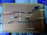
 I just build this driver today and i was checking to make sure it is good before I start soldering the connections.  I used a free online photo editing software so if you cant tell what the words say just tell me....Here it is...(sorry if the picture sucks...i dont have a camera so i had to take the picture on my iPhone and email it to myself...sorry) can I solder the connections under the breadboard?
  Thanks again!
 

Attachments

  • Drive2r.jpg
    Drive2r.jpg
    101.8 KB · Views: 83
I was getting really bored so i went ahead and soldered everything (i took my time...it took me like 2 hours...) but i finally finished it and i tested it out on an LED and it worked very well :)....I took a risk and attached my diode....And thats when things went terribly fantastic ;D...It lit up and made a really really really bright dot on the wall where it was aimed. It is great i can adjust the lense and everything...But...it wont burn..Any suggestions?
Thanks again
 
The_Muffin_Man said:
I was getting really bored so i went ahead and soldered everything (i took my time...it took me like 2 hours...) but i finally finished it and i tested it out on an LED and it worked very well :)....I took a risk and attached my diode....And thats when things went  terribly fantastic ;D...It lit up and made a really really really bright dot on the wall where it was aimed.  It is great i can adjust the lense and everything...But...it wont burn..Any suggestions?
Thanks again

How many milliAmps are you running through it? The PHR diode will burn at a fairly low power output.

Are you sure you have it focused? The 405nm makes a VERY small point when it is focused correctly.

Peace,
dave
 
thanks for your fast response...to tell you the truth I am not sure how many milliamps I am running though it...how do I check? And would adjusting the pot help?
I will work on focusing it and see if that is the problem...
Thanks


Back
Top